Video wall signal echo method and system
A splicing wall and signal display technology, applied in closed-circuit television systems, TV system components, image communications, etc., can solve problems affecting processor image output, large signal access, complex configuration, etc., to reduce network bottlenecks problem effect
- Summary
- Abstract
- Description
- Claims
- Application Information
AI Technical Summary
Problems solved by technology
Method used
Image
Examples
Embodiment 2
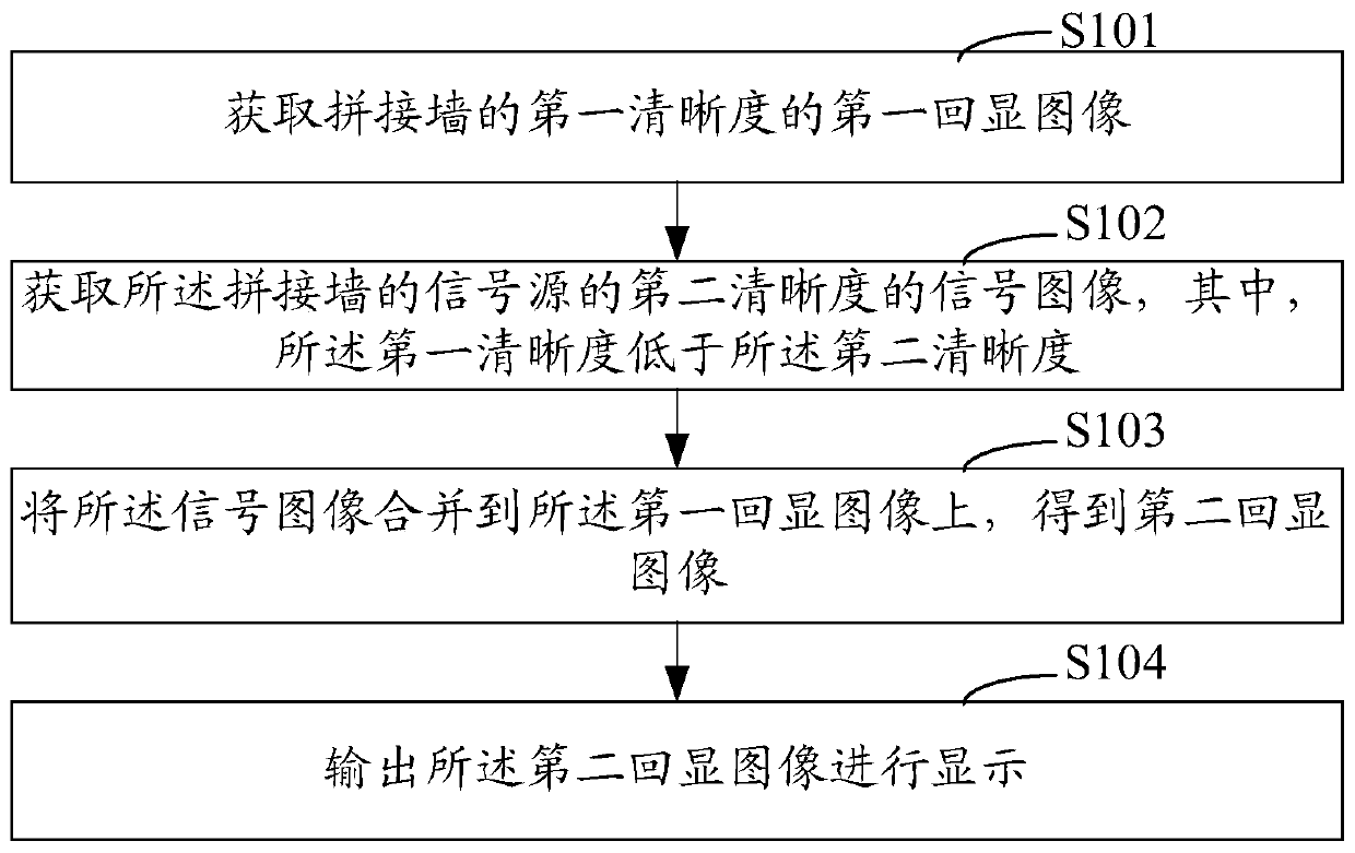
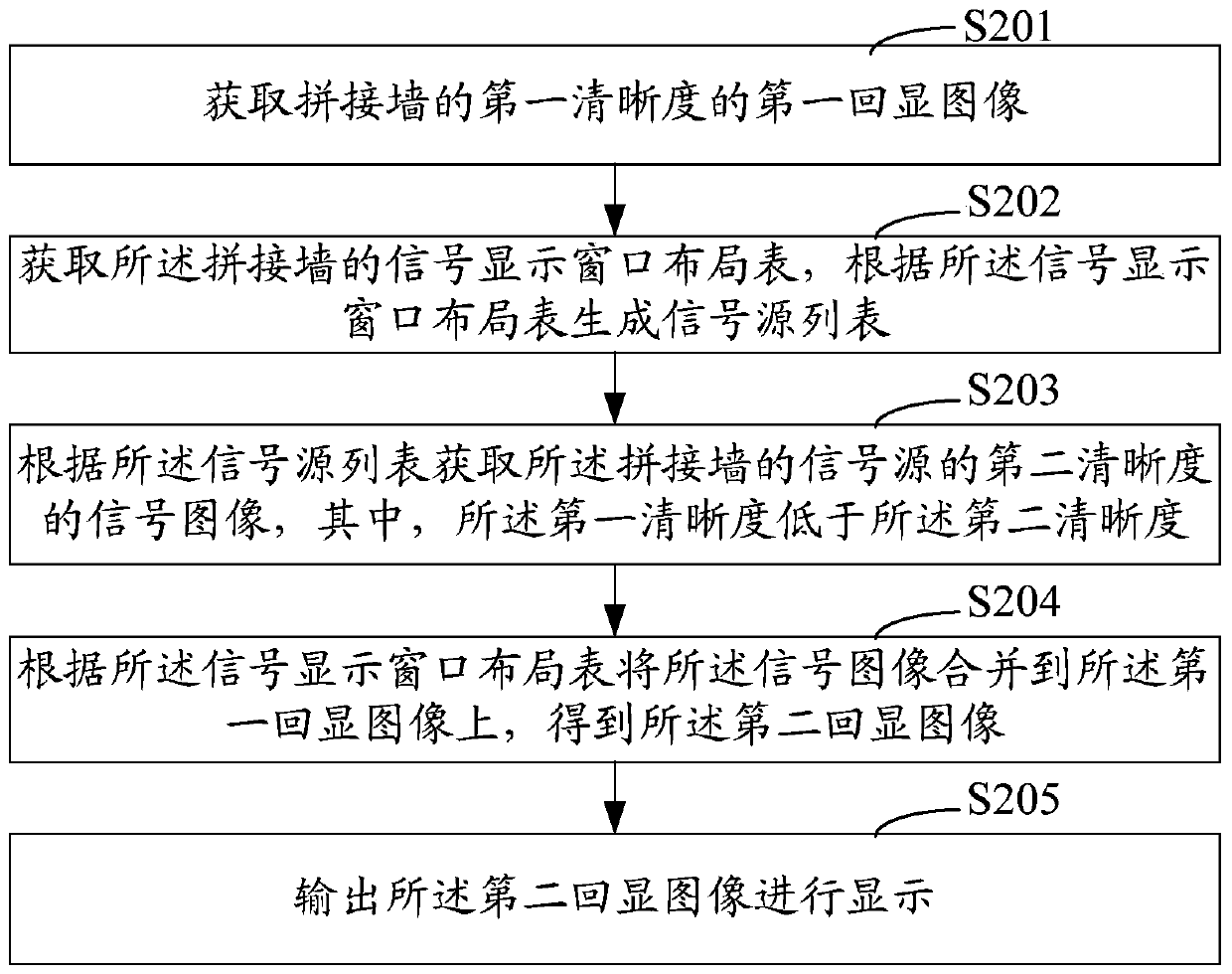
[0045] see figure 2 As shown, it is a schematic flowchart of Embodiment 2 of the video wall signal echo method of the present invention. In this embodiment, the main difference from the first embodiment above is that it takes into account the need to acquire the signal image and merge the signal image into the first echo image, that is to say, it is necessary to know the current signal source information of the video wall (what signal sources are there) and the position information of the display windows opened by these signal sources on the splicer. For this reason, in this embodiment, the step of obtaining the signal display window layout table of the video wall is added, which can facilitate the video wall The current signal source information and the position information of these signal sources on the display window opened on the splicer.
[0046] Such as figure 2 As shown, the video wall signal echo method in the second embodiment includes the following steps:
[004...
Embodiment 3
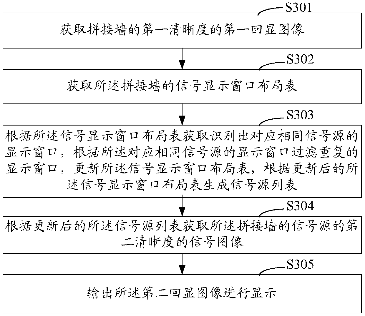
[0057] see image 3 As shown, it is a schematic flowchart of Embodiment 3 of the video wall signal echo method of the present invention. In this embodiment, the main difference from the second embodiment above is that, considering that there may be multiple display windows corresponding to the same signal source in the signal display window layout table initially obtained from the control server, if repeated to When the signal source or the signal preview server obtains the display image, the resource consumption of the signal source or the signal preview server will be increased. For this reason, in the third embodiment, the step of filtering and filtering repeated display windows is added, which can reduce the need for the signal source or signal preview server. Signal preview server resource consumption.
[0058] Such as image 3 As shown, the video wall signal echo method in the third embodiment includes the following steps:
[0059] Step S301: Acquiring the first echo ...
Embodiment 4
[0068] Such as Figure 4 As shown, it is a schematic flowchart of Embodiment 4 of the video wall signal echo method of the present invention. In this embodiment, the main difference from the first embodiment above is that, considering that the initial size of the first echoed image is often inconsistent with the output size of the echoed image, for this reason, in this embodiment, the addition of A step of adjusting the size of the first echoed image to the output size.
[0069] Such as Figure 4 As shown, the video wall signal echo method in Embodiment 4 includes the following steps:
[0070] Step S401: Acquiring the first echo image of the first definition of the video wall;
[0071] Step S402: Obtain the output size of the echoed image, and adjust the size of the first echoed image to the output size;
[0072] The echo image here may refer to the first echo image or the second echo image;
[0073] The adjustment here can refer to zooming in or zooming out, but consider...
PUM
 Abstract
Description
Claims
Application Information
 - R&D
- Intellectual Property
- Life Sciences
- Materials
- Tech Scout
- Unparalleled Data Quality
- Higher Quality Content
- 60% Fewer Hallucinations
Browse by: Latest US Patents, China's latest patents, Technical Efficacy Thesaurus, Application Domain, Technology Topic, Popular Technical Reports.
© 2025 PatSnap. All rights reserved.Legal|Privacy policy|Modern Slavery Act Transparency Statement|Sitemap|About US| Contact US: help@patsnap.com


