
Geared continuously variable transmission

A technology of continuously variable speed change mechanism and speed change mechanism, which is applied in the direction of gear transmission, belt/chain/gear, mechanical equipment, etc., and can solve problems such as speed change impact

Inactive Publication Date: 2015-09-16
松村秀树
View PDF10 Cites 1 Cited by
  • Summary
  • Abstract
  • Description
  • Claims
  • Application Information

AI Technical Summary

Problems solved by technology

For the stepped speed change, there is known such as clutch-type technology, that is, to prepare two groups of intermittent devices for engine power and the corresponding gear sets, and to make it ready for the next shift gear in advance before shifting gears, so as to obtain the next shift gear in a short time. Shifting gears and making the transmission efficiency good, but basically in the stepped transmission, the acceleration required for the next gear shift needs to be achieved by increasing the rotational speed, and the power transmission will be interrupted when the gear is changed. In terms of energy efficiency There are problems, and there will be a shift shock, so a continuously variable transmission is preferred

Method used


Image

  • Geared continuously variable transmission
  • Geared continuously variable transmission
  • Geared continuously variable transmission

Examples


Embodiment

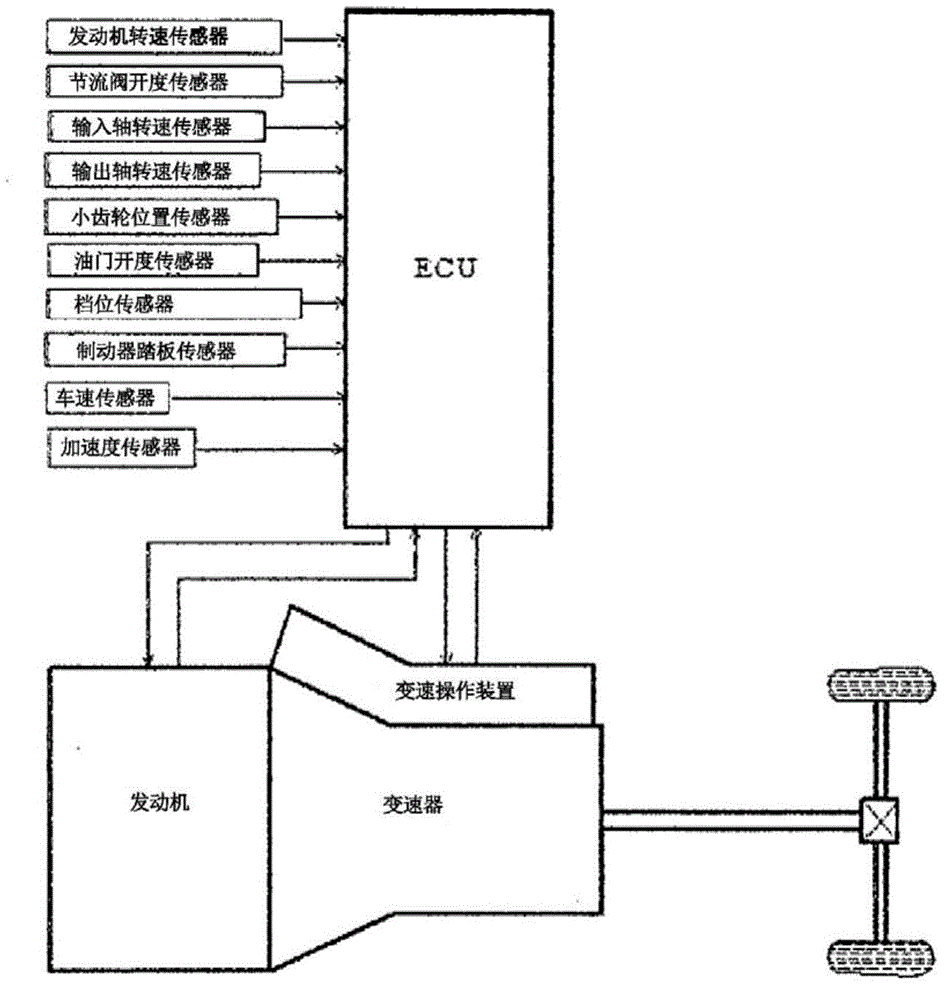
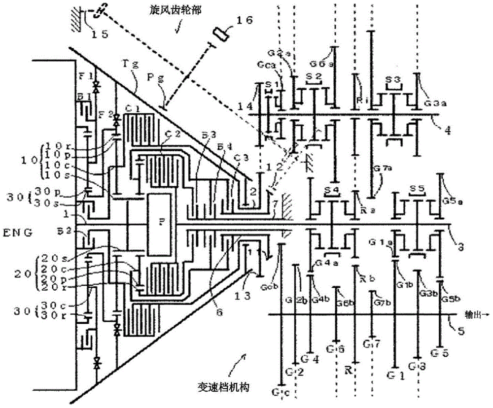
[0063] figure 1 It is a schematic configuration diagram of an automatic transmission for a vehicle as a first example according to an embodiment of the present invention. The rotational torque is transmitted to the drive wheels via the differential gear. It should be noted that the engine is preferably an engine capable of outputting high torque from low speed rotation.

[0064] The electronic control unit ECU includes a CPU, a ROM, a RAM, a backup RAM, and the like, and the ROM stores various control programs, information maps that are referred to when executing these control programs, and the like. The CPU executes arithmetic processing based on various control programs and information maps stored in the ROM. The RAM is a memory for temporarily storing calculation results of the CPU, data input from each sensor, etc., and the backup RAM is a non-volatile memory for storing data to be saved when the engine is stopped. These mechanisms are connected to each other via a bus,...


PUM


Abstract

The present invention achieves a mechanical mission having more favorable power transmission efficiency than existing versions, and has a reduced environmental impact. The present invention enables continuously variable shifting by means of gears by means of being provided with: a continuously variable transmission mechanism that is geared and that results from a spiral gear (Tg) and a second gear (Pg); a braking means that brakes a drive means that drives the second gear and the spiral gear; and a switching means that switches same. Furthermore, the present invention can be put to actual use as a geared continuously variable transmission device by means of being provided with: a motive power distributing mechanism that distributes the motive power of a motive power source; a motive power combining mechanism that combines motive power output from the geared continuously variable transmission mechanism that uses the distributed motive power; a gear range mechanism that discontinuously shifts the motive power and outputs the result; and a means that switches between a pathway that includes the geared continuously variable transmission mechanism and a pathway that does not.

Description

【Technical field】 [0001] The present invention relates to a continuously variable transmission mechanism capable of continuously changing the rotational speed ratio, particularly utilizing a gear mechanism. 【Background technique】 [0002] An internal combustion engine has a rotational speed range with the highest efficiency, and it is preferable to maintain the rotational speed range within this rotational speed range from the viewpoints of fuel consumption efficiency and power performance. Therefore, also in a vehicle or the like employing an internal combustion engine or the like as a power source, it is preferable to use a rotational speed region with high efficiency as much as possible. [0003] In order to utilize the high-efficiency rotation range of the power source, power transmission is realized by using a transmission that can perform a wide-ranging speed change operation from low-speed running to high-speed running. For example, conventionally known as transmissi...

Claims


Application Information

Patent Timeline
Patent Type & Authority Applications(China)
IPC IPC(8): F16H3/42F16H3/093F16H37/02
CPCF16H3/423F16H37/084F16H61/66F16H3/66F16H3/093
Inventor 松村秀树
Owner 松村秀树
Learn More