A cylinder valve wrench

A cylinder valve, first-hand technology, applied in the field of cylinder valve wrench, can solve the problems of palm damage and difficult to twist, and achieve the effect of increasing friction

Active Publication Date: 2017-03-01
INST OF BOTANY CHINESE ACAD OF SCI
View PDF5 Cites 0 Cited by
  • Summary
  • Abstract
  • Description
  • Claims
  • Application Information

AI Technical Summary

Problems solved by technology

[0002] Many existing chemical analysis instruments need to use steel cylinders to supply gas when they are in use. Since there is no special cylinder valve tool, the valve can only be twisted by hand when replacing the steel cylinder. However, because the valve is tightened and sealed, it is often encountered Case that is difficult to twist and therefore easily injures the palm

Method used


Image

  • A cylinder valve wrench
  • A cylinder valve wrench
  • A cylinder valve wrench

Examples


Embodiment Construction

[0014] The present invention will be described in detail below in conjunction with the accompanying drawings and embodiments.

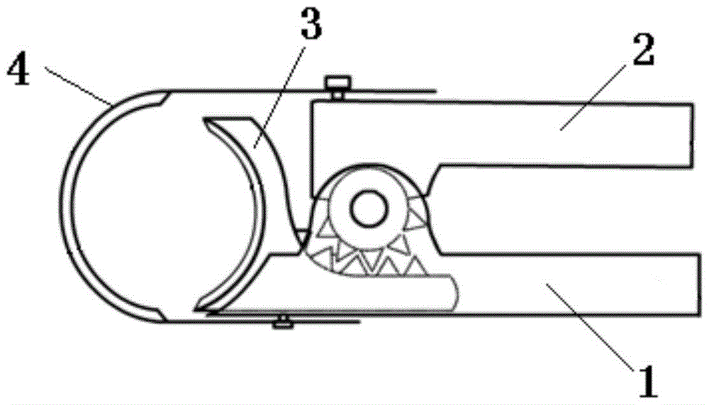
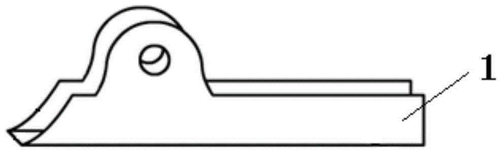
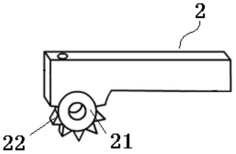
[0015] Such as figure 1 , figure 2 As shown, the present invention includes a first handle 1 and a second handle 2, and the first handle 1 and the second handle 2 are rotatably connected through a pivot shaft. At the pivotal end of the second handle 2, an annular part 21 (such as image 3 As shown), the outer side of the annular component 21 is evenly provided with a plurality of gear teeth 22 along the circumferential direction, and the inner hole of the annular component 21 is used for nesting the pivot shaft. A chute capable of accommodating the tightening slider 3 is provided on the first handle 1 .

[0016] Clamping slider 3 comprises a straight section 32 and an arc section 31 integrally arranged at one end of the straight section 32 (such as Figure 4 shown), wherein, the opening direction of the circular arc section 31 deviates from the p...


PUM


Abstract

The present invention relates to a steel cylinder valve wrench, and is characterized in that the steel cylinder valve wrench comprises a first handle and a second handle pivoted to the first handle; a pivot end of the second handle is provided with an annular part; an outer side of the annular part is uniformly provided with a plurality of first gear teeth along the circumferential direction; the first handle is provided with a chute for accommodating a clamping slide block; the clamping slide block comprises a straight segment and an arc segment integratedly disposed at one end of the straight segment; an opening direction of the arc segment departs from the pivot end; one side of the straight segment is provided with a plurality of gear teeth engaged with the first gear teeth; outer sides of the first handle and the second handle are commonly connected with a U-shaped clamping annular plate; and an opening of the clamping annular plate is arranged opposite to the opening of the arc segment of the clamping slide block. Due to the fact that the pivot end of the second handle is provided with the gear teeth, and the clamping slide block is provided with the gear teeth engaged with the gear teeth of the second handle, a steel cylinder valve can be clamped more firmly when the handles are held.

Description

technical field [0001] The invention relates to a cylinder valve wrench, which belongs to the field of chemical equipment. Background technique [0002] Many existing chemical analysis instruments need to use steel cylinders to supply gas when they are in use. Since there is no special cylinder valve tool, the valve can only be twisted by hand when replacing the steel cylinder. However, because the valve is tightened and sealed, it is often encountered A case that is difficult to twist and therefore easily injures the palm. Contents of the invention [0003] In view of the above problems, the object of the present invention is to provide a steel cylinder valve wrench which is easy to operate and can be applied to valves of different sizes. [0004] To achieve the above object, the present invention adopts the following technical solutions: a steel cylinder valve wrench, characterized in that it includes a first handle and a second handle, the first handle is pivotally con...

Claims


Application Information

Patent Timeline
Patent Type & Authority Patents(China)
IPC IPC(8): B25B13/48
CPCB25B13/48
Inventor 刘伟苏华张淑敏赵长征韩文武
Owner INST OF BOTANY CHINESE ACAD OF SCI
Why Eureka
Try Eureka