Supercharge Your Innovation With Domain-Expert AI Agents!

Hydraulic tensioning device

A tensioning device and hydraulic technology, applied in the field of hydraulic tensioning devices, to achieve the effects of low cost, reduced wear and simple structure

Inactive Publication Date: 2015-09-23
WUXI SUNDA INTELLIGENT AUTOMATION & ENG COMPANY
View PDF9 Cites 4 Cited by
  • Summary
  • Abstract
  • Description
  • Claims
  • Application Information

AI Technical Summary

Problems solved by technology

The telescopic track is welded on one side of the movable frame

Method used


Image

  • Hydraulic tensioning device
  • Hydraulic tensioning device
  • Hydraulic tensioning device

Examples


Embodiment Construction

[0013] Below the present invention will be further described in conjunction with the embodiment in the accompanying drawing:

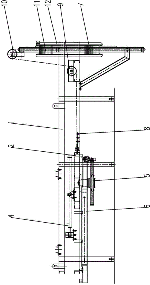
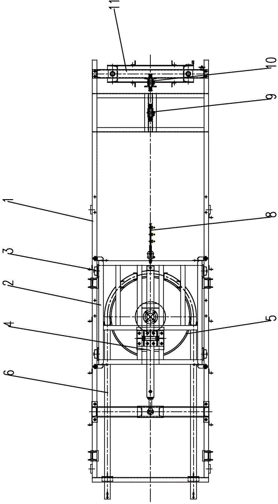
[0014] Such as Figure 1~2 As shown, the present invention mainly includes a fixed frame 1 and a movable frame 2. The movable frame 2 is slidably connected in the fixed frame 1 through the pulleys 3 on both sides. , the rotating light wheel 5 plays a role in rotating the chain.

[0015] A hydraulic cylinder 4 is fixed on the fixed frame 1, and the front end of the piston rod of the hydraulic cylinder 4 is connected with the movable frame 2. The hydraulic cylinder 4 is connected to a hydraulic system, and the hydraulic cylinder 4 is driven by the hydraulic system to push the movable frame 2 to move forward and backward along the fixed frame 1 .

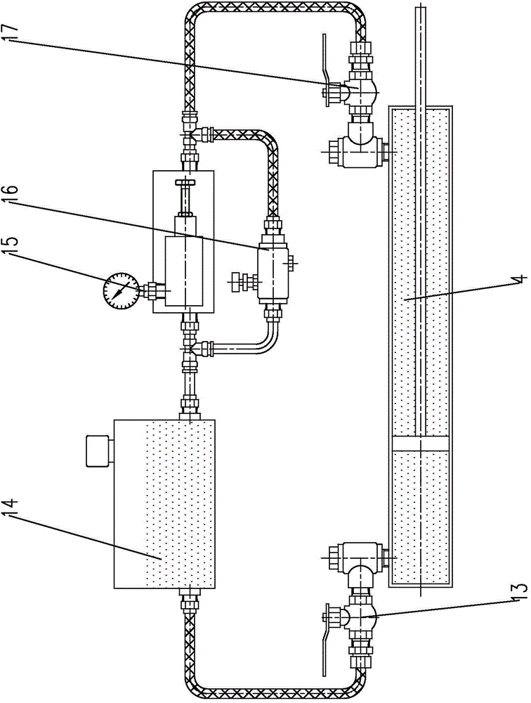
[0016] Such as image 3 As shown, the hydraulic system includes a first ball valve 13 connected to the rodless chamber of the hydraulic cylinder 4 and a second ball valve 17 connected to the rod chamber of t...


PUM


Abstract

The invention relates to a hydraulic tensioning device, in particular to the hydraulic tensioning device used in a chain conveyer and belongs to the technical field of chain conveyer chain tensioning. The hydraulic tensioning device comprises a fixed frame and a movable frame, wherein a hydraulic cylinder is fixed to the fixed frame, the front end of a piston rod of the hydraulic cylinder is connected with the movable frame, the hydraulic cylinder is connected with a hydraulic system, the hydraulic cylinder is driven by the hydraulic system, and therefore the movable frame is pushed to move back and forth along the fixed frame; the rear end of the movable frame is connected with a balance weight mechanism, and a certain initial tension is provided for a chain on a revolution smooth wheel through the balance weight mechanism. The hydraulic tensioning device is simple, compact and reasonable in structure, capable of adjusting the tension in the chain at any time and reducing the abrasion to a track by the chain and convenient to use and install; the tension of the chain is controlled through a hydraulic mechanism, no compressed air is needed to be equipped, and the cost is low.

Description

technical field [0001] The invention relates to a hydraulic tensioning device, in particular to a hydraulic tensioning device used on a chain conveyor, belonging to the technical field of conveyor chain tensioning. Background technique [0002] In the prior art, aerial accumulation conveyors are widely used in pre-treatment of automobile bodies and electrophoresis lines. Since there are many ups and downs in the line body to meet the requirements of the process, the tension in the chain will change with the different positions of the spreader, so it is required that the tensioning device can adjust the tension in the chain at any time, and at the same time avoid the negative load on the chain. tension, and the tension in the chain must not be too high. The heavy hammer tensioning structure that adopts in the present technology, its defect is that heavy hammer has very big tension force to chain all the time, causes the wearing and tearing aggravation to track. Contents of...

Claims


Application Information

Patent Timeline
IPC IPC(8): B65G23/44
CPCB65G23/44
Inventor 高建飞陆雷兵
Owner WUXI SUNDA INTELLIGENT AUTOMATION & ENG COMPANY
Features
  • R&D
  • Intellectual Property
  • Life Sciences
  • Materials
  • Tech Scout
  • Unparalleled Data Quality
  • Higher Quality Content
  • 60% Fewer Hallucinations
Learn More