
Pay-off frame and pay-off method

A pay-off rack and wire-loading technology, which is used in the transportation of filamentous materials, thin material handling, transportation and packaging, etc., can solve the problem of unsecured wire tension, reduce workload, increase work efficiency, increase The effect of the service life

Pending Publication Date: 2019-09-20
优易电缆(张家港)有限公司
View PDF0 Cites 0 Cited by
  • Summary
  • Abstract
  • Description
  • Claims
  • Application Information

AI Technical Summary

Problems solved by technology

[0003] The purpose of the present invention is to provide a pay-off stand, which is used to solve the problem that the tension of the wires in the prior art cannot be guaranteed

Method used


Image

  • Pay-off frame and pay-off method
  • Pay-off frame and pay-off method
  • Pay-off frame and pay-off method

Examples


Embodiment 1

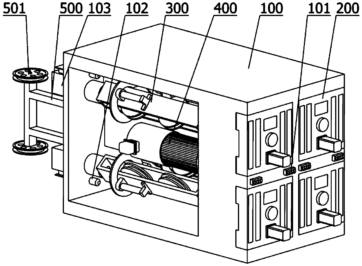
[0048] Such as figure 1 As shown, this embodiment discloses a wire pay-off frame, which includes: a main body, a wire loading frame, a rotating part, and a fixing frame. Main body, there is a working indicator light on the front of the main body, the working indicator light is used to indicate the working state of the pay-off rack, and there is a rotary air joint behind the main body, which can input the compressed air into the cylinder, and the main body has Accommodate space. The fixed frame has two fixed frames, and the upper and lower ends of the fixed frame are provided with outgoing wire guide wheels, which are used to lead out the wires.

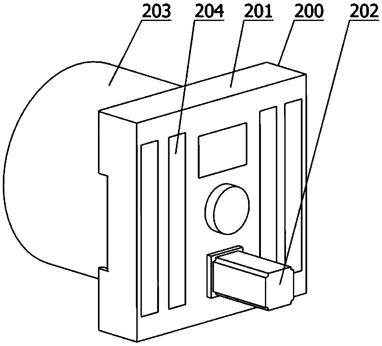
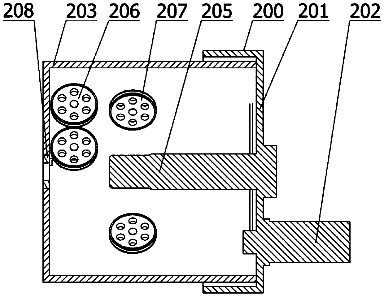
[0049] Such asfigure 1 , 2 , 3, and 4, this embodiment discloses a pay-off rack, wherein the wire rack has:

[0050] The wire frame cover is installed on the front of the main body, the wire frame cover is used to install and close the wire reel, and the wire frame cover is equipped with a pay-off motor, which is used to release th...


PUM


Abstract

The invention discloses a pay-off frame and relates to the technical field of wire and cable production. The pay-off frame comprises a main body, wire loading frames, a rotating part and fixing frames, wherein operating indication lamps are arranged on the front surface of the main body and used for indicating an operating state of the pay-off frame; the main body is internally provided with a containing space; the wire loading frames are mounted on the front surface of the main body and used for loading wire coils; the rotating part is mounted in a position opposite to the main body and used for allowing a wire to keep constant tension; and the fixing frames are mounted on the back surface of the main body. The pay-off frame can guarantee the tension of the wire, allow subunits in the wire to keep the constant tension and therefore ensure that the produced wire is longer in service life.

Description

technical field [0001] The invention relates to the technical field of wire and cable production, in particular to a pay-off frame and a pay-off method. Background technique [0002] In wire and cable factories or rope production enterprises, etc., the produced wire, cable or rope needs to be wound on the wire reel for storage and transportation. When the wire is processed, the wire reel needs to be placed on the pay-off rack to let the wire enter the stranded wire Machines and other equipment for processing, but the current domestic pay-off racks are not able to maintain a stable tension, often tight and loose, will cause unstable factors to product quality. Contents of the invention [0003] The purpose of the present invention is to provide a wire pay-off stand, which is used to solve the problem that the tension of the wires cannot be guaranteed in the prior art. [0004] The second purpose of the present invention is to provide a wire-laying method. [0005] In orde...

Claims


Application Information

Patent Timeline
IPC IPC(8): B65H49/18B65H57/06B65H57/14B65H59/10
CPCB65H49/18B65H57/06B65H57/14B65H59/10B65H2701/34
Inventor 俞俊李金涛谢清心齐刚
Owner 优易电缆(张家港)有限公司
Learn More