
Spray Axial Fans with Sidewall Spray Tubes

A technology of axial fans and water spray pipes, which is applied in the field of fluid mechanical devices, can solve the problems of narrow operating range, reduced fan flow and efficiency, and large pipe resistance of spray fans, so as to reduce the energy consumption of moving blades and improve Total pressure, efficiency, and low vibration effect

Active Publication Date: 2017-10-20
深圳市熙诚环保科技有限公司
View PDF4 Cites 0 Cited by
  • Summary
  • Abstract
  • Description
  • Claims
  • Application Information

AI Technical Summary

Problems solved by technology

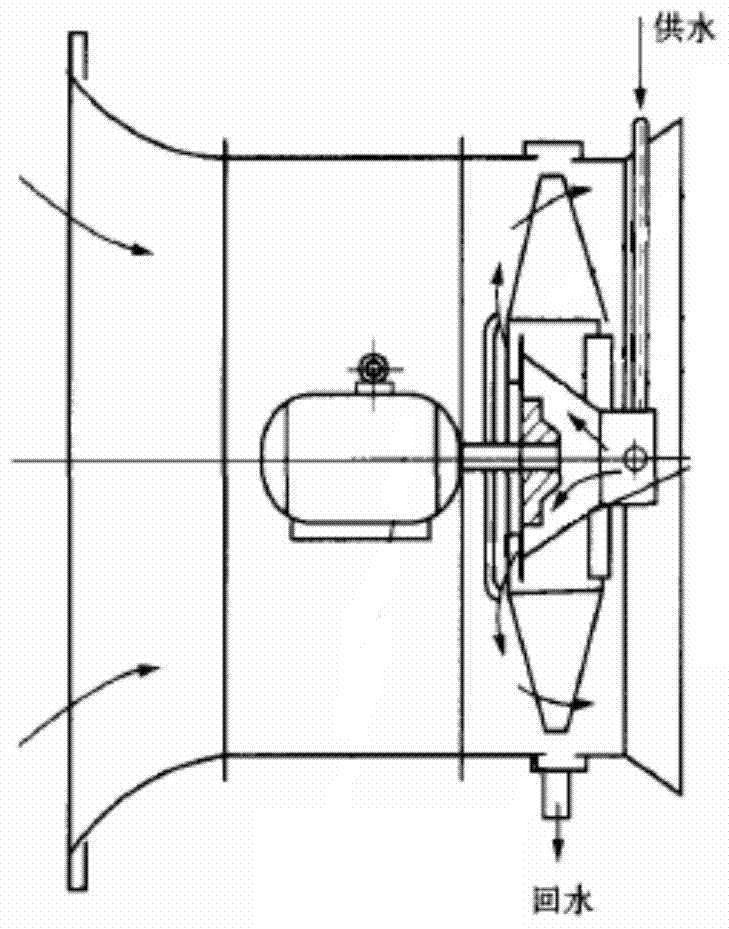
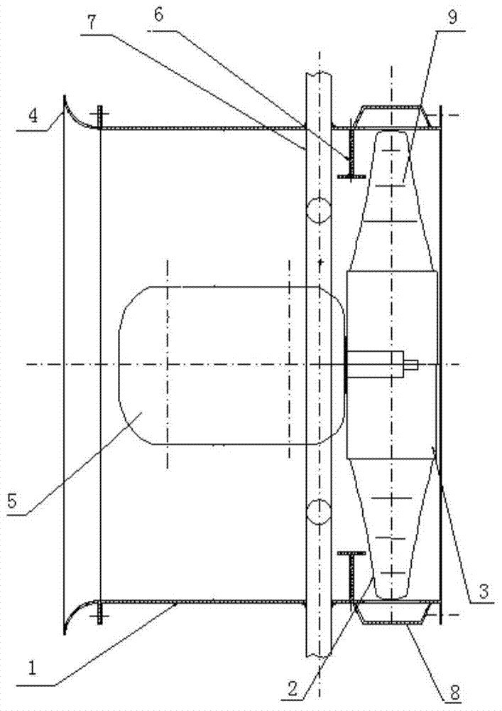
The spray axial flow fan effectively improves the figure 1 The energy consumption of the fan increases and the efficiency decreases under the condition of a large water-air ratio of the spray fan. However, the setting of the water spray ring at the inlet of the spray axial flow fan greatly increases the resistance of the fan flow channel, disturbs the airflow at the inlet of the impeller, and causes the fan to fail. The flow rate and efficiency are significantly reduced, and the ring water spray pipe is easy to vibrate and loosen under the impact of high-speed airflow, so further improvement is needed
[0006] Although the appearance of the spray axial flow fan has greatly reduced the power consumption of the old textile air conditioning system, the spray fan, as the key equipment of the new textile air conditioning system, has its own narrow range of working conditions for the water-air ratio of the traditional spray fan. The improved pipe resistance of the spray fan has many problems such as a large drop in efficiency

Method used


Image

  • Spray Axial Fans with Sidewall Spray Tubes
  • Spray Axial Fans with Sidewall Spray Tubes
  • Spray Axial Fans with Sidewall Spray Tubes

Examples


Embodiment Construction

[0023] The structure and working principle of the present invention will be further described in detail below with reference to the accompanying drawings and specific embodiments.

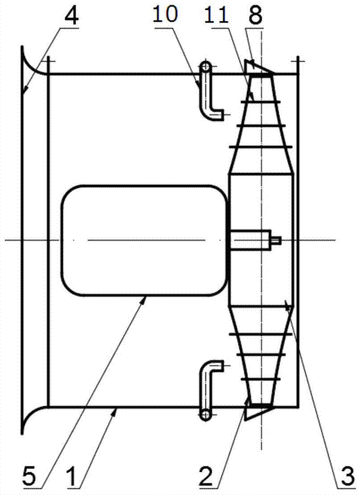
[0024] refer to image 3 , a spray axial fan with a side wall water spray pipe, including a collector 4, a fan duct 1, a motor 5, a hub 3, a moving blade 2 and a water-repellent grid 8, before the impeller inlet, the motor 5 and the hub 3 Between the inner and outer walls of the fan duct, a side wall water spray pipe 10 is arranged, and a radial water blocking device 11 is arranged on the moving blade 2 .

[0025] refer to Figure 4 , the side wall water spray pipe 10 is composed of a water delivery ring pipe 13 placed on the outer wall of the fan duct and a plurality of water spray pipe heads 12 extending into the inner wall of the fan duct, and each water spray pipe head is connected with the water delivery ring pipe. 13 is connected, and a plurality of water spray pipe heads are evenly distrib...


PUM


Abstract

The invention discloses a spraying axial flow fan with a side wall water spray pipe, which comprises a current collector, a blower fan cylinder, a motor, a wheel hub, moving blades and a drain grid, and radial water retaining devices are arranged on the moving blade blades. It is characterized in that, between the motor and the hub, a side wall water spray pipe is arranged, and the side wall water spray pipe inputs water flow through an annular water delivery pipe located outside the blower fan cylinder, and the side wall water spray pipe extends into the spray pipe inside the fan blower cylinder. The water outlet of the water pipe head faces the moving blade, and sprays water to the rotating moving blade along the axial direction. Due to the arrangement of the side wall water spray pipe and the radial water retaining device, compared with the existing spray axial flow fan, the axial flow spray fan of the present invention can significantly improve the efficiency of the fan and reduce the power consumption of the motor.

Description

technical field [0001] The invention relates to a fluid mechanical device, in particular to a spray axial flow fan. Background technique [0002] Axial spray fans are used in many industries. In the textile industry, in order to maintain the temperature and humidity of the textile workshop and ensure the quality of textile products, an air conditioning device must be set up. The widely used textile air-conditioning system now takes the traditional spray fan as the core. Through a large number of fine water droplets generated by the spray fan, the water mist droplets and the air are directly exchanged for heat and mass, so as to adjust the humidity and temperature of the air to achieve the purpose of air conditioning . The traditional spray fan integrates the air supply function of the general fan and the function of generating spray. It is an axial flow fan formed by installing a spray device on the basis of the ordinary axial flow fan. The basic structure of the traditio...

Claims


Application Information

Patent Timeline
Patent Type & Authority Patents(China)
IPC IPC(8): F04D25/08F04D29/00F24F5/00
Inventor 李景银熊琎崔浩禹
Owner 深圳市熙诚环保科技有限公司
Learn More