bypass filter

A filter and oil filter tank technology, applied in the field of hydraulic machinery, can solve problems such as the inability of the filter to adapt and the blockage of different oil pressures.

Active Publication Date: 2017-11-10
PRO PURE HONG KONG LTD
View PDF7 Cites 0 Cited by
  • Summary
  • Abstract
  • Description
  • Claims
  • Application Information

AI Technical Summary

Problems solved by technology

[0003] In view of the above problems, the purpose of the present invention is to provide a bypass filter, aiming to solve the technical problem that the existing filter cannot adapt to different oil pressures and is easy to cause clogging

Method used


Image

  • bypass filter
  • bypass filter
  • bypass filter

Examples


Embodiment Construction

[0013] In order to make the object, technical solution and advantages of the present invention clearer, the present invention will be further described in detail below in conjunction with the accompanying drawings and embodiments. It should be understood that the specific embodiments described here are only used to explain the present invention, not to limit the present invention.

[0014] In order to illustrate the technical solutions of the present invention, specific examples are used below to illustrate.

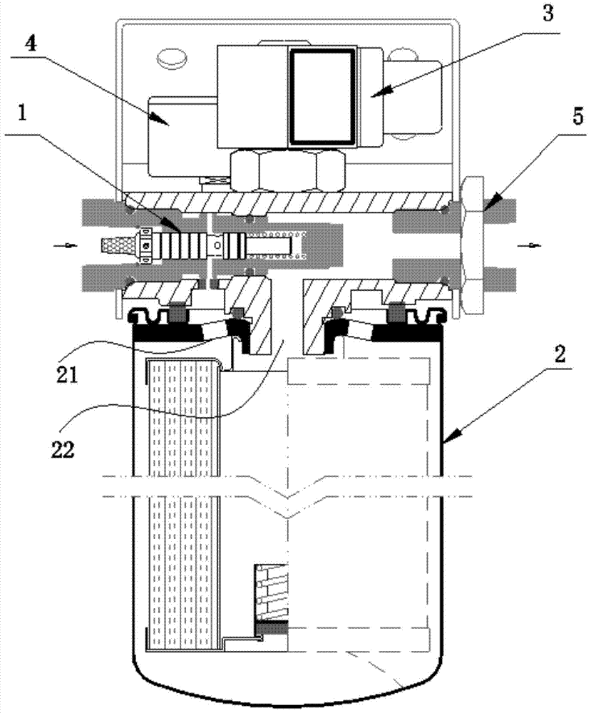
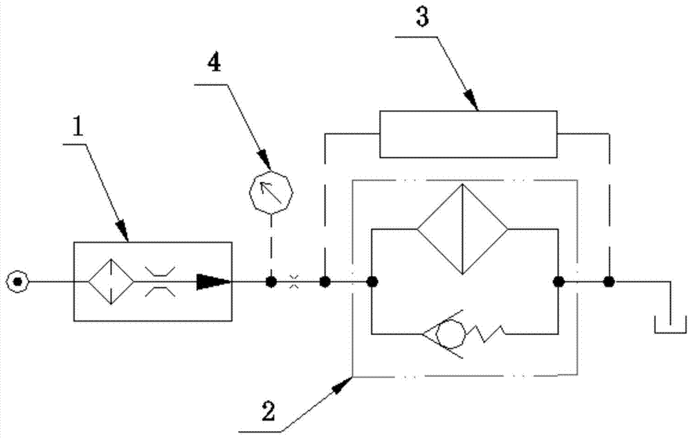
[0015] figure 1 The structure of the bypass filter provided by the embodiment of the present invention is shown, figure 2 The principle of the bypass filter is shown, and only the part related to the embodiment of the present invention is shown for convenience of description.

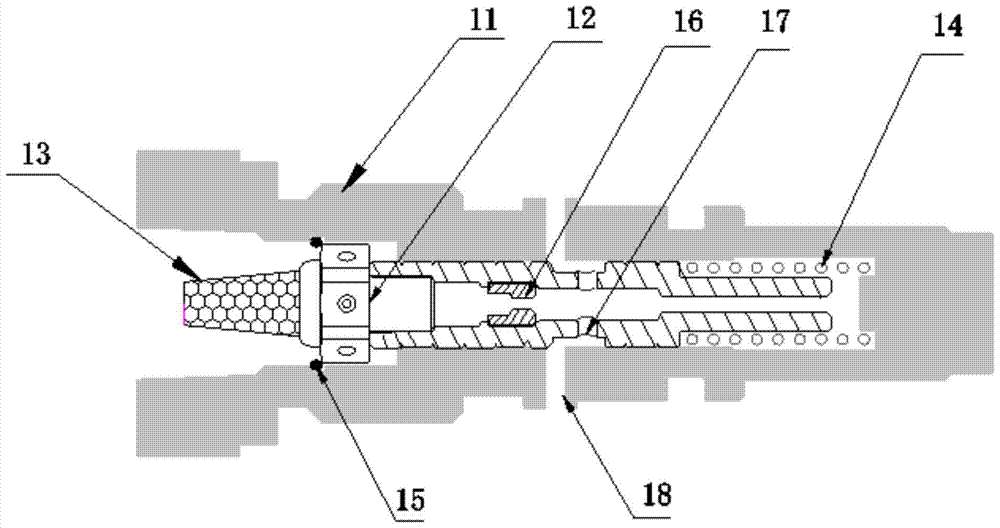
[0016] refer to figure 1 with figure 2 The bypass filter provided in this embodiment includes a flow control valve 1, an oil filter tank 2 installed below the flow control valve, an oil filt...


PUM


Abstract

The invention is suitable for the field of hydraulic machinery, and provides a bypass type filter. The bypass type filter comprises a flow control valve, an oil filter tank installed below the flow control valve and a differential pressure transmission device arranged between an inlet and an outlet of the oil filter tank; a pressure gauge is connected with a channel between an outlet of the flow control valve and the inlet of the oil filter tank, an inlet of the flow control valve serves as an oil inlet connector of the bypass type filter, and the bypass type filter further comprises an oil outlet connector which is communicated with the outlet of the oil filter tank. The bypass type filter can adapt to different oil pressure, and whether the pressure size of the oil inlet connector changes or not, the flow at the oil outlet is at the standard set value. According to the preferable scheme, an iron prop is arranged in the differential pressure transmission device, a magnetic reed pipe can be induced after a magnetic body and the iron prop are mutually attracted, and the transmission consistency of each product is guaranteed.

Description

technical field [0001] The invention belongs to the technical field of hydraulic machinery, in particular to a bypass filter. Background technique [0002] In the hydraulic system, due to equipment wear and other reasons after long-term use, there will be some impurities in the oil, which will affect the service life of the hydraulic machine. For this reason, a bypass is generally drawn from the hydraulic system, and then a filter is installed. The flow control valve controls the flow by controlling the opening and closing of the valve, but it cannot adapt to oil pressures of different pressures, and there is no coarse filter, which may easily cause blockage of the flow control valve. Contents of the invention [0003] In view of the above problems, the purpose of the present invention is to provide a bypass filter, which aims to solve the technical problem that the existing filter cannot adapt to different oil pressures and is prone to clogging. [0004] The present inve...

Claims


Application Information

Patent Timeline
Patent Type & Authority Patents(China)
IPC IPC(8): F15B21/04
CPCF15B21/041
Inventor 郭云开
Owner PRO PURE HONG KONG LTD
Why Eureka
Try Eureka