Flexible flywheel
A flexible flywheel and signal disc technology, applied in the direction of flywheel, spring/shock absorber, vibration suppression adjustment, etc., to offset axial shock and torsional vibration, ensure stiffness, reduce part cost and weight
- Summary
- Abstract
- Description
- Claims
- Application Information
AI Technical Summary
Problems solved by technology
Method used
Image
Examples
Embodiment Construction
[0017] Below in conjunction with accompanying drawing and embodiment the present invention is further described:
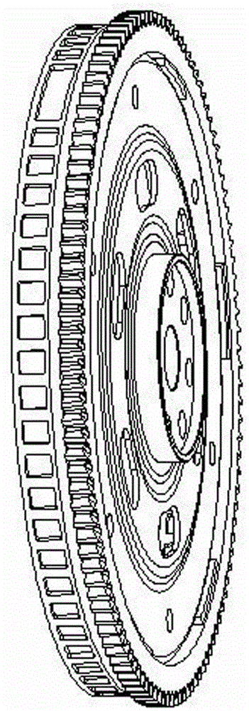
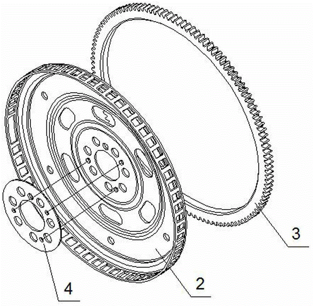
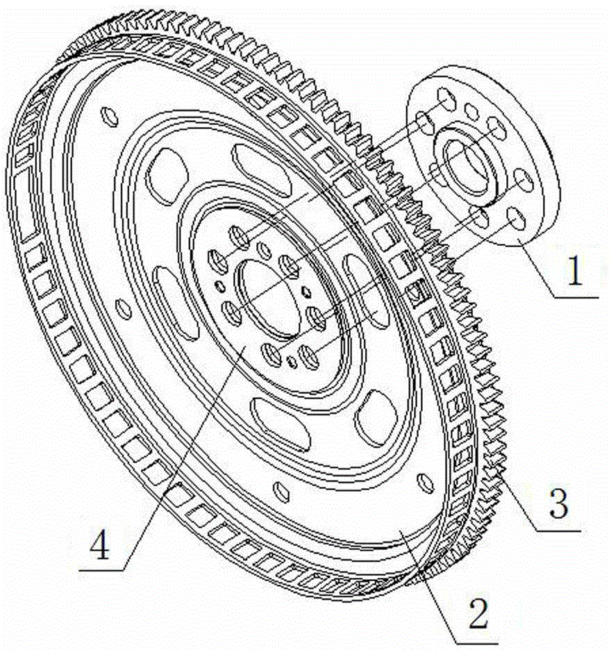
[0018] figure 1 , figure 2 and image 3 The flexible flywheel includes a connecting flange 1, a signal plate 2, a start tooth 3 and a pressure plate 4; the pressure plate 4 is fixed on the middle of one side of the signal plate 2 by riveting, and the start tooth 3 is fixed on the signal plate 2 by welding On the other side; then the signal plate 2 and the connecting flange 1 are fixed on the output end of the engine crankshaft by bolts; the signal plate 2 is arranged with a reinforcing rib in the forward and reverse directions, and the forward reinforcing rib 7 faces the pressure plate 4. Slightly protruding in the direction, and 6 long oval-shaped material removal holes 5 are evenly distributed on the upper circumference of the reverse rib 6 to optimize its rigidity; 58 signal teeth are distributed on the signal plate 2, and the width of each tooth is 5.1 mm; ...
PUM
| Property | Measurement | Unit |
|---|---|---|
| Width | aaaaa | aaaaa |
Abstract
Description
Claims
Application Information
 - R&D
- Intellectual Property
- Life Sciences
- Materials
- Tech Scout
- Unparalleled Data Quality
- Higher Quality Content
- 60% Fewer Hallucinations
Browse by: Latest US Patents, China's latest patents, Technical Efficacy Thesaurus, Application Domain, Technology Topic, Popular Technical Reports.
© 2025 PatSnap. All rights reserved.Legal|Privacy policy|Modern Slavery Act Transparency Statement|Sitemap|About US| Contact US: help@patsnap.com


