
Lamp with variable focal lengths

A lamp and variable technology, applied in the parts, lighting devices, light sources and other directions of the lighting device, can solve the problems such as the mechanical movement mechanism is prone to noise, the control relies on direct drive, the lamp structure is complex, etc., and achieves strong maintainability, The effect of easy operation and simplified design

Active Publication Date: 2015-09-23
APUTURE IMAGING IND CO LTD
View PDF5 Cites 3 Cited by
  • Summary
  • Abstract
  • Description
  • Claims
  • Application Information

AI Technical Summary

Problems solved by technology

However, the existing variable-focus LED lamps are all equipped with many complex mechanical motion mechanisms to change the light-emitting surface, which not only makes the structure of the lamp complex and increases the cost, but also the mechanical motion mechanisms are prone to noise, and the control depends on direct drive

Method used


Image

  • Lamp with variable focal lengths
  • Lamp with variable focal lengths
  • Lamp with variable focal lengths

Examples


Embodiment Construction

[0011] The structural principle of the present invention will be described below in conjunction with the accompanying drawings and embodiments.

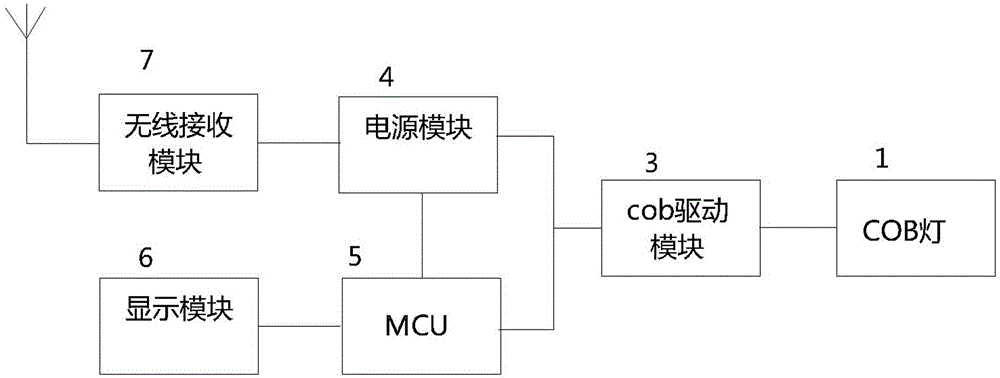
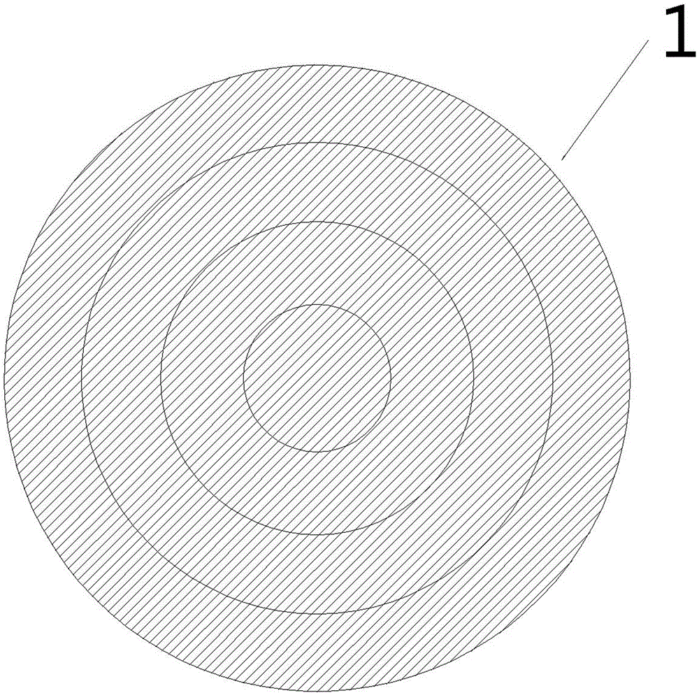
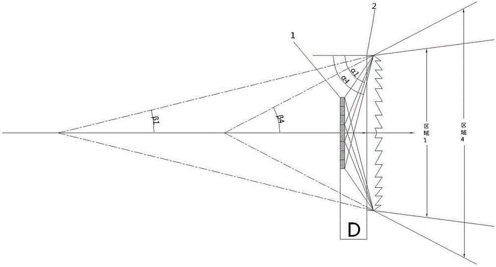
[0012] Such as figure 1 , figure 2 As shown, the variable-focus lamp of the present invention includes: a COB lamp (board) 1 with two or more ring structures, a Fresnel lens 2 made of transparent materials such as PE, PMMA, and glass, and a COB lamp controlled by an MCU 5 A driving module 3 , a wireless receiving module 7 , a display module 6 , and a power module 4 .

[0013] Among them, the COB lamp of this embodiment adopts a 4-turn (ring) structure, the power supply module 4, the COB drive module 3 and the COB lamp 1 are electrically connected in sequence, and the Fresnel lens 2 is arranged on one side of the light-emitting plane of the COB lamp 1, and The distance D from the COB lamp 1 is less than one focal length, which refracts the light emitted by the COB lamp.

[0014] Such as image 3 As shown, the MCU 5 controls the C...


PUM


Abstract

The invention discloses an electronic zooming device for an LED lamp, and particularly relates to a lamp with the variable focal lengths. The lamp comprises a power module, a COB driving module, a COB lamp with at least two circles of annular structures and a lens arranged on one side of a light-emitting plane of the COB lamp. The distance between the lens and the COB lamp is smaller than one focal length. An MCU controls the different circles of the COB lamp to be turned on, so that the incident angle of the COB lamp relative to a Fresnel lens is changed by changing the number of the turn-on circles of the COB lamp when the distance between the COB lamp and the lens is kept identical; therefore, variable focal lengths can be obtained by changing the cover area of light-emitting light within the same distance. According to the technical scheme, the mute LED lamp with the variable focal lengths and the all-electronic design is obtained.

Description

technical field [0001] The invention relates to an LED lamp, in particular to a variable-focus LED lamp. Background technique [0002] With the development of LED technology, LED has many outstanding characteristics compared with traditional light sources, which makes the application of LED lights in various industries respond to the demand. LED lights with various functions emerge in endlessly, and LED lights that can realize zoom function are also one of them. [0003] The principle of the LED light that can realize the zoom function is to change the distance between the light-emitting surface and the Fresnel lens. However, the existing variable-focus LED lamps are all equipped with many complex mechanical motion mechanisms to change the light-emitting surface, which not only makes the structure of the lamp complex and increases the cost, but also the mechanical motion mechanisms are prone to noise, and the control depends on direct drive. Contents of the invention ...

Claims


Application Information

Patent Timeline
Patent Type & Authority Applications(China)
IPC IPC(8): F21S2/00F21V14/00F21V23/04F21Y101/02
CPCF21V14/00F21V23/0435
Inventor 谢奕
Owner APUTURE IMAGING IND CO LTD
Learn More