
An aircraft engine fuel simulation control system and adjustment method

A technology of aircraft engine and fuel system, which is applied in the direction of engine testing, machine/structural component testing, instruments, etc., to achieve the effect of high parameter accuracy and simple operation

Active Publication Date: 2018-07-24
XI'AN AIRCRAFT INTERNATIONAL
View PDF5 Cites 0 Cited by
  • Summary
  • Abstract
  • Description
  • Claims
  • Application Information

AI Technical Summary

Problems solved by technology

[0005] The purpose of the present invention is to solve the problems of fuel consumption simulation and flow regulation of the fuel system under various working conditions

Method used


Image

  • An aircraft engine fuel simulation control system and adjustment method

Examples


Embodiment Construction

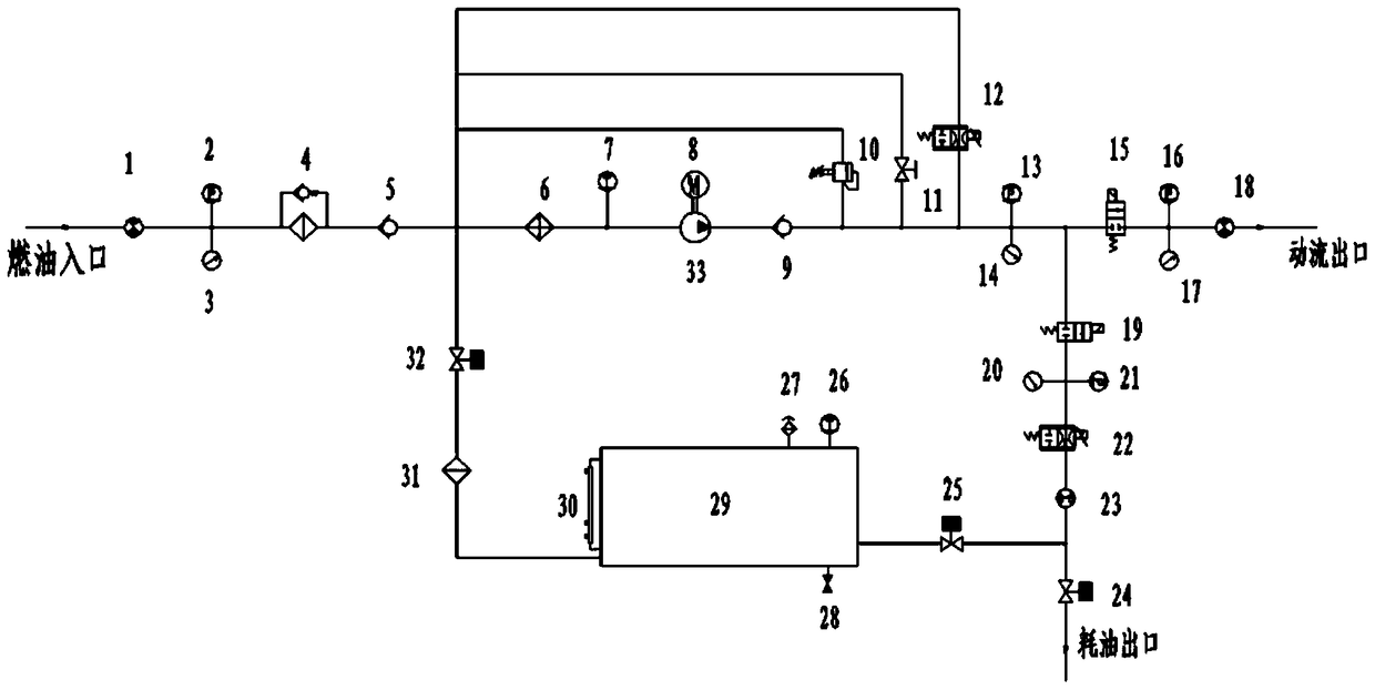
[0024] Such as figure 1 As shown, the aircraft engine fuel simulation control system includes a system pressure regulation pipeline, a dynamic flow simulation pipeline, and a fuel consumption pipeline; the upstream of the system pressure regulation pipeline is connected to the fuel outlet of the aircraft fuel system, and the downstream is connected to the outlet of the system pressure regulating valve 10 ;Connect the inlet flowmeter 1, inlet pressure sensor 2, inlet pressure gauge 3, inlet filter 4, inlet check valve 5, cooling device 6, temperature sensor 7, and frequency conversion motor to the system pressure regulating pipeline along the direction of fuel flow. 8. Check valve 9, system pressure sensor 13, and system pressure gauge 14 are connected in parallel to the system pressure regulating valve 10, safety Valve 11, dynamic flow pressure regulating valve 12; outlets of system pressure sensor 13 and system pressure gauge 14 are connected in parallel with dynamic flow sim...


PUM


Abstract

The invention provides an aircraft engine fuel simulation control system and its adjustment method. The system includes a system pressure adjustment pipeline, a dynamic flow simulation pipeline, and a fuel consumption pipeline; various regulating valves on the pipeline are used for flow regulation and simulation . The present invention is a system with simple operation and high parameter accuracy, which can not only simulate the fuel consumption of the engine alone, but also combine the fuel consumption and provide a set of dynamic flow, and is suitable for simulating the fuel consumption of various types of engines. The inspection function can carry out the self-circulation work of the equipment before the joint test with the system to verify whether it can reach the working state.

Description

technical field [0001] The invention relates to the field of aircraft engine control systems, in particular to an aircraft engine fuel simulation control system and an adjustment method. Background technique [0002] With the expansion of a certain type of aircraft fleet and the continuous increase in flight hours, many problems and failures have been exposed to the fuel system during field operations. [0003] There are many defects in the existing engine fuel simulation control system. For example: the dynamic flow pressure is displayed by a pointer pressure gauge, and due to the rough switch adjustment, the dynamic flow pressure and flow are unstable, which makes the pressure display error larger. In addition, the original analog system only has pressure display, no flow information, and cannot be accurate Simulate the real working state of the engine, so the functional verification of the fuel system cannot be performed qualitatively and can only be used quantitatively....

Claims


Application Information

Patent Timeline
Patent Type & Authority Patents(China)
IPC IPC(8): G01M15/02
Inventor 时亚文席睿绚张红艳
Owner XI'AN AIRCRAFT INTERNATIONAL
Learn More