
Current transformer waveform monitoring device and current transformer control system

A technology of monitoring devices and converters, applied in measuring devices, digital variable/waveform displays, instruments, etc., can solve problems such as inconvenient portability, large oscilloscope volume, limited oscilloscope observation channels, etc., and achieve high real-time performance and high precision Effect

Inactive Publication Date: 2015-09-23
CSR ZHUZHOU ELECTRIC LOCOMOTIVE RES INST
View PDF9 Cites 0 Cited by
  • Summary
  • Abstract
  • Description
  • Claims
  • Application Information

AI Technical Summary

Problems solved by technology

However, this way of observing the waveform through the oscilloscope needs to use cables to transmit the data of the sensor to the oscilloscope, and this also causes secondary wiring at the user site, which affects the debugging efficiency of the converter
At the same time, the observation channels of the oscilloscope are limited. If there are many physical quantities to be observed, multiple oscilloscopes may be needed
In addition, due to the relatively large size of the oscilloscope, it is also inconvenient to carry

Method used


Image

  • Current transformer waveform monitoring device and current transformer control system
  • Current transformer waveform monitoring device and current transformer control system
  • Current transformer waveform monitoring device and current transformer control system

Examples


Embodiment Construction

[0026] The embodiments of the present invention will be described in detail below with reference to the accompanying drawings and examples, so as to fully understand and implement the implementation process of how the present invention applies technical means to solve technical problems and achieve technical effects. It should be noted that, as long as there is no conflict, each embodiment of the present invention and each feature of each embodiment can be combined with each other, and the formed technical solutions all fall within the protection scope of the present invention.

[0027] Meanwhile, in the following description, for the purposes of explanation, numerous specific details are set forth in order to provide a thorough understanding of the embodiments of the present invention. It will be apparent, however, to those skilled in the art that the present invention may be practiced without the specific details or in the specific manner described herein.

[0028] In view o...


PUM


Abstract

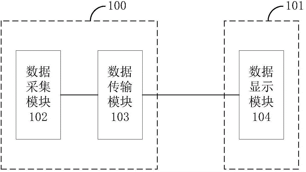
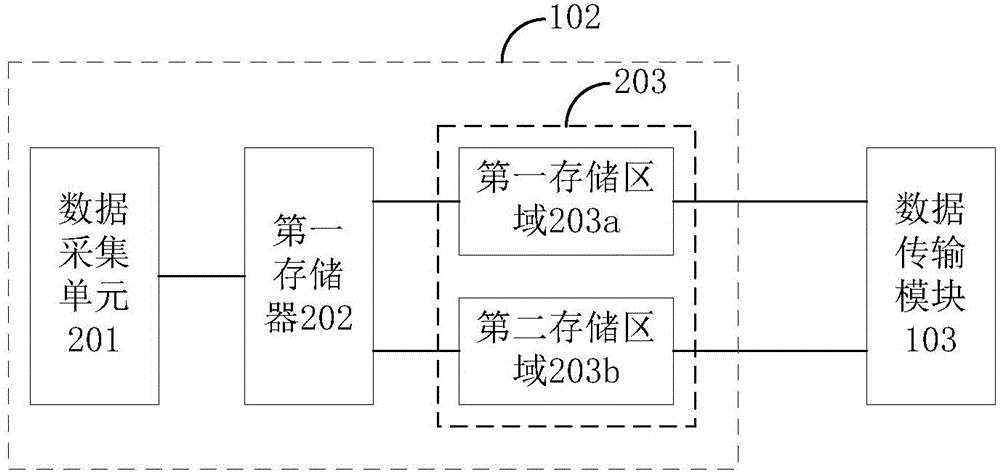
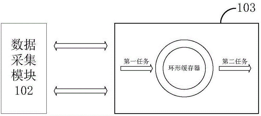
The invention discloses a current transformer waveform monitoring device and a current transformer control system. The monitoring device comprises a data acquisition module which acquires current transformer operation state related data required to be monitored in each operation cycle of a current transformer control algorithm according to the current transformer control algorithm so that monitoring data are obtained; a data acquisition module which is connected with the data acquisition module and used for converting the monitoring data according to the preset communication protocol; and a data display module which is connected with the data transmission module and used for visually displaying the data transmitted by the data transmission module so that current transformer waveform monitoring is realized. Compared with existing waveform monitoring devices, the device is high in real-time performance, and waveform of voltage and current outputted by the current transformer can be monitored in real time. Other hardware equipment does not need to be carried by debugging personnel when the waveform of the current transformer is monitored.

Description

technical field [0001] The invention relates to the technical field of automatic detection, in particular to a converter waveform monitoring device and a converter control system. Background technique [0002] During the debugging of the converter, it is necessary to observe the waveforms of physical quantities such as current, voltage, and rotational speed at the load terminal in real time, so as to adjust the parameters of the converter according to these waveforms, so that the performance of the converter can meet the actual needs of users. [0003] At present, monitoring the waveforms of physical quantities such as voltage, current, and rotational speed at the load end of the converter mainly adopts an oscilloscope to observe the waveforms of physical quantities converted by sensors. However, this method of observing the waveform through the oscilloscope requires the use of cables to transmit the sensor data to the oscilloscope, which also results in secondary wiring at ...

Claims


Application Information

Patent Timeline
IPC IPC(8): G01R13/00
Inventor 陈俊波戴计生郑良广徐绍龙李程李益罗凌波吕阳李雪江李泽泉
Owner CSR ZHUZHOU ELECTRIC LOCOMOTIVE RES INST
Learn More