Position control system based on steel wire rope driving

A control system and wire rope technology, applied in the field of multi-motor synchronous control system, can solve problems such as large return error, and achieve the effect of reducing overall mass and driving power

Active Publication Date: 2015-09-23
BEIHANG UNIV
View PDF5 Cites 4 Cited by
  • Summary
  • Abstract
  • Description
  • Claims
  • Application Information

AI Technical Summary

Problems solved by technology

This is because the wire rope has great elasticity in the process of transmission. If it is used in the precise position control system of reciprocating motion, it will bring a large return error. Therefore, the traditional wire rope transmission is rarely used in the precise position control of reciprocating motion. occasion

Method used


Image

  • Position control system based on steel wire rope driving
  • Position control system based on steel wire rope driving

Examples


Embodiment Construction

[0016] Embodiments of the present application are described below with reference to the drawings. Elements and features described in one drawing or one embodiment of the present application may be combined with elements and features shown in one or more other drawings or embodiments. It should be noted that representation and description of components and processes that are not relevant to the present application and known to those of ordinary skill in the art are omitted from the drawings and descriptions for the purpose of clarity.

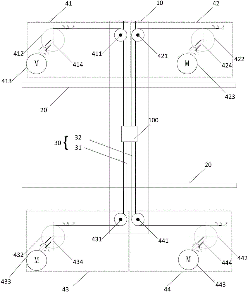
[0017] Such as figure 1 Shown is a schematic structural diagram of a position control system based on wire rope transmission according to an embodiment of the present application.

[0018] In this embodiment, the position control system based on wire rope transmission includes a longitudinal guide rail 10, a transverse guide rail 20, a wire rope set 30 and driving devices 41-44.

[0019] Wherein, the longitudinal guide rail 10 is slidably conn...


PUM


Abstract

The invention relates to a position control system based on steel wire rope driving, which comprises a longitudinal guide rail, transverse guide rails, a steel wire rope group and driving devices, wherein the longitudinal guide rail is slidably connected with the transverse guide rails; the steel wire rope group is connected with a controlled mobile platform and the driving devices, and used for driving the controlled mobile platform to move along the longitudinal guide rail based on a driving force outputted by the driving devices. According to the scheme provided by the invention, longitudinal and transverse positions of the controlled mobile platform can be controlled accurately.

Description

technical field [0001] This application relates to a multi-motor synchronous control system, especially a position control system based on wire rope transmission. Background technique [0002] In the prior art, commonly used transmission modes include timing belt transmission, chain transmission, pull rod transmission and wire rope transmission. [0003] Compared with other transmission methods, wire rope transmission has the advantages of light weight, high efficiency, and small footprint. Therefore, it is of great significance to use wire rope transmission to achieve precise position control of objects. [0004] Existing wire rope drives are mainly used in mine hoisting and aircraft control systems. [0005] When used in mine hoisting, the steel wire rope is only subjected to one-way tension, and mine hoisting does not require high positioning accuracy. [0006] When applied to the aircraft control system, the wire rope drive uses two wire ropes. During the reciprocating...

Claims


Application Information

Patent Timeline
Patent Type & Authority Applications(China)
IPC IPC(8): G05D3/12
Inventor 郭全焦宗夏严亮尚耀星
Owner BEIHANG UNIV
Why Eureka
Try Eureka