
Subsynchronous oscillation suppression device and method based on phase-locked loop error

A technology of subsynchronous oscillation and suppression device, applied in the field of synchronous machines, can solve the problem of inability to suppress subsynchronous oscillation, and achieve the effects of effective detection and rapid response, good controllability and error reduction.

Inactive Publication Date: 2015-09-23
STATE GRID CORP OF CHINA +3
View PDF5 Cites 34 Cited by
  • Summary
  • Abstract
  • Description
  • Claims
  • Application Information

AI Technical Summary

Benefits of technology

This patented technology allows for precise timing adjustment between two electrical machines connected together without any interference from other devices like motors or generators. By utilizing this system, there are no physical contact needed during operation while ensuring accurate alignment with each other's movements. Additionally, the use of advanced techniques called Phase Lock Loop Error has been developed to improve upon current systems. Overall, these technical features enhance efficiency and reliability in electricity generation equipment.

Problems solved by technology

Technological Problem: The technical problem addressed in this patented paper relates to prevention of subsynchronization between two phases of an AC motor driven electric generating station when subjected to submerged DC link failure due to fluctuating voltages from overlapping parts of active elements like diodes and transistor components.

Method used


Image

  • Subsynchronous oscillation suppression device and method based on phase-locked loop error
  • Subsynchronous oscillation suppression device and method based on phase-locked loop error
  • Subsynchronous oscillation suppression device and method based on phase-locked loop error

Examples


Embodiment Construction

[0033] In order to make the object, technical solution and advantages of the present invention clearer, the present invention will be further described in detail below in conjunction with the accompanying drawings and embodiments. It should be understood that the specific embodiments described here are only used to explain the present invention, not to limit the present invention.

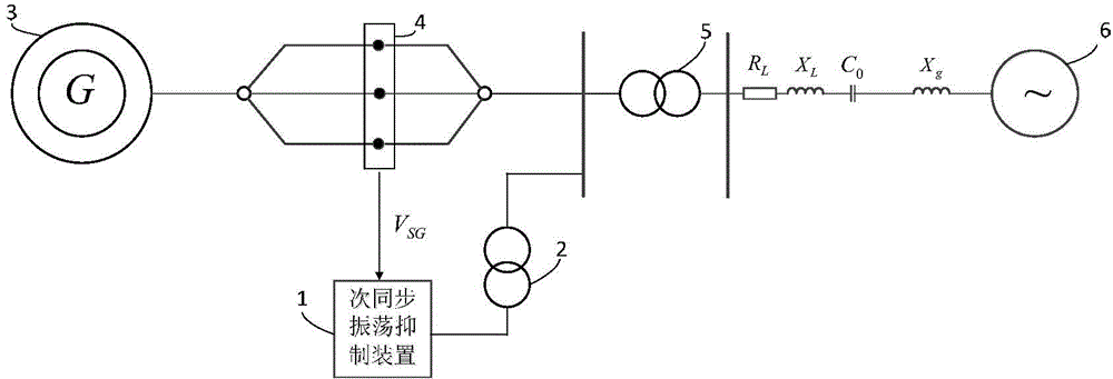
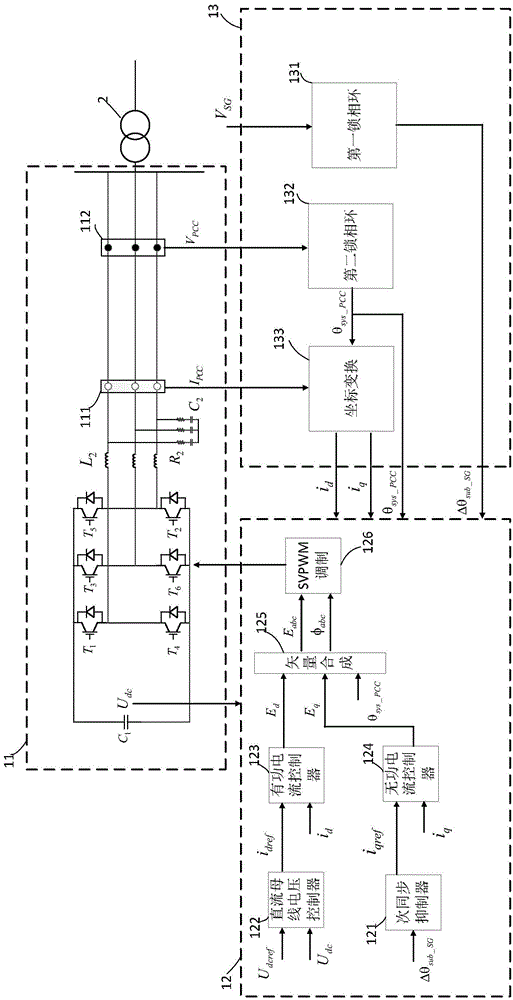
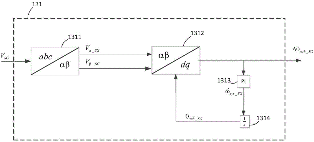
[0034] The present invention relates to a new type of sub-synchronous suppression method applied to thermal power units based on the parallel connection of fully-controlled switching devices, and more specifically relates to a detection of sub-synchronous oscillation components in the outlet voltage of synchronous machines by relying on phase-locked loop errors. By injecting the reactive current component of the same mode into the power grid to adjust the port voltage of the synchronous machine, and then adjust the active power of the synchronous output to achieve the control method of suppressing t...


PUM


Abstract

The invention provides a subsynchronous oscillation suppression device and method based on a phase-locked loop error. The subsynchronous oscillation suppression device comprises a three-phase inverter, a control module and a signal detection module, wherein a first input end of the signal detection module is used for receiving the three-phase AC voltage of a synchronizer port, a second input end is used for receiving the three-phase AC voltage of a device port, a third input end is used for receiving the three-phase AC current of the device port, a first input end of the control module is connected to a first output end of the signal detection module, a second input end of the control module is used for receiving a DC bus voltage, a third input end of the control module is connected to a third output end of the signal detection module, a fourth input end of the control module is connected to a fourth output end of the signal detection module, a fifth input end of the control module is connected with a second output end of the signal detection module, the control module is used for further adjusting electrical damping size through control of reactive current according to a phase-locked error signal obtained by the signal detection module, so that the subsynchronous oscillation of a system is suppressed.

Description


Claims


Application Information

Patent Timeline
Owner STATE GRID CORP OF CHINA
Features
  • Generate Ideas
  • Intellectual Property
  • Life Sciences
  • Materials
  • Tech Scout
  • Unparalleled Data Quality
  • Higher Quality Content
  • 60% Fewer Hallucinations
Learn More