Insertion part for endoscope and endoscope

A technology of endoscope and insertion part, applied in the direction of endoscope, application, medical science, etc., can solve the problems of increased filling rate, hindering the bending action of the bending part, etc., and achieve the effect of shortening the length of the tube

Active Publication Date: 2017-12-29
FUJIFILM CORP
View PDF8 Cites 0 Cited by
  • Summary
  • Abstract
  • Description
  • Claims
  • Application Information

AI Technical Summary

Problems solved by technology

In the case where the confluence member is disposed in the endoscope insertion portion as in the endoscopes described in Patent Documents 3 to 5, if the liquid supply tube and the gas supply tube, or the branch pipe portion of the confluence member are disposed in the curved portion, , the filling rate increases compared with the case where the air supply and liquid supply pipes are arranged, and the bending action of the bending part may be hindered

Method used


Image

  • Insertion part for endoscope and endoscope
  • Insertion part for endoscope and endoscope
  • Insertion part for endoscope and endoscope

Examples


no. 1 approach

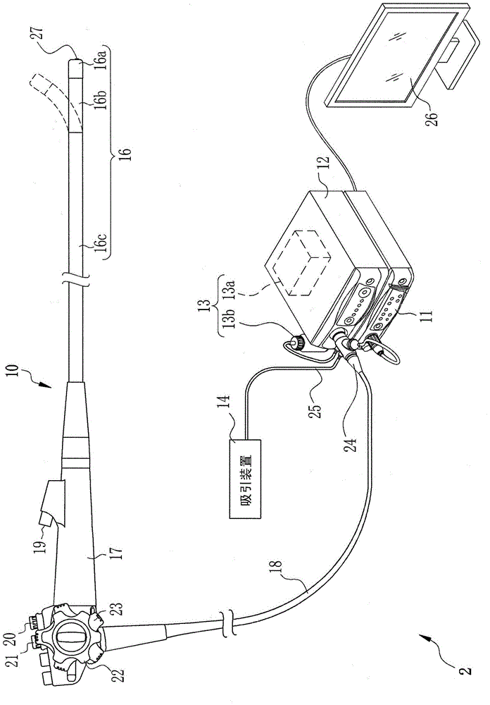
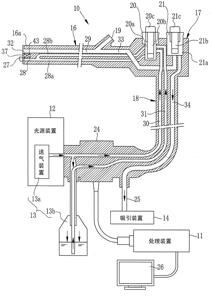
[0065] like figure 1 As shown, the endoscope system 2 includes an electronic endoscope 10 , a processing device 11 , a light source device 12 , an air and liquid feeding device 13 , and a suction device 14 . The gas and liquid feeding device 13 includes a known gas feeding device (pump, etc.) 13 a built in the light source device 12 to send gas, and a liquid tank 13 b provided outside the light source device 12 to store liquid. The electronic endoscope 10 has a flexible endoscope insertion portion (hereinafter referred to as an insertion portion) 16 inserted into the body, a manual operation portion 17 connected to the base end portion of the insertion portion 16, and a processing device 11, The universal cord 18 to which the light source device 12 is connected. Washing water is used as the liquid conveyed by the air and liquid feeding device 13 , and air and carbon dioxide gas are used as the conveyed gas.

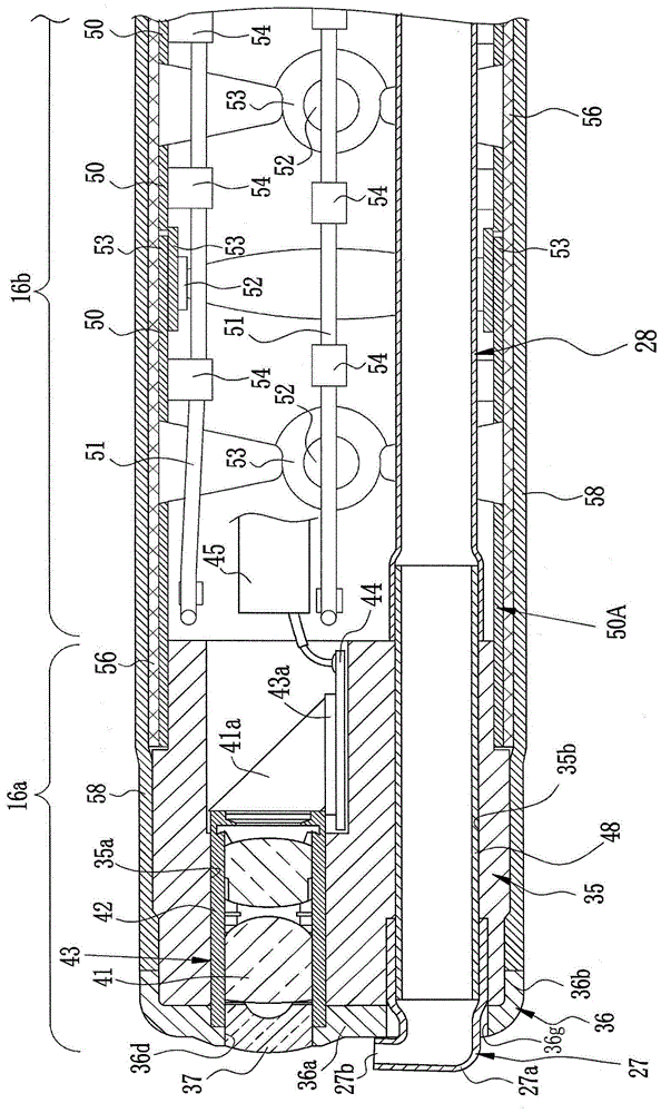
[0066] The insertion part 16 has a front end part 16a, a bent part...

no. 2 approach

[0102] In the above-mentioned first embodiment, the positions of the branch tube parts 71a and 71b are limited by the arrangement of built-in components such as the signal cable 45, the light guides 46a and 46b, the treatment instrument insertion tube 29, the coil tube 55, and the fixing part 60 as an example. Be explained. However, it is not limited to this, it can also be like Figure 9 Like the base end block 75 constituting the insertion portion of the second embodiment shown, the protruding portion 76 protruding from the fixing portion 60 toward the confluence member 70 is integrally formed. Since the contents in the insertion part 16 slightly move according to the bending operation of the bending part 16b and the insertion shape of the soft part 16c, in the above-mentioned first embodiment, there is a possibility that the branch pipe parts 71a, 71b may enter the proximal end. space within block 50B, but in this second embodiment, as Figure 10 As shown, by bringing the...

no. 3 approach

[0104] In addition, as another example of restricting the position of the branch pipe parts 71a, 71b, it is also possible to Figure 11 As in the third embodiment shown, a spring 80 as an urging member is provided between the coil tube 55 and the confluence member 70 . In this case, the spring 80 is attached so that one end is wound around the coil tube 55 and the other end is wound around the junction pipe part 72 . Thereby, when the confluence member 70 is pulled in by the bending of the bent portion 16b, the spring 80 biases the confluence member 70 toward the proximal end side of the soft portion 16c. By the action of the spring 80 , it is possible to restrict the entry of the branch pipe portions 71 a and 71 b into the base end block 50B and to return to the position of the confluence member 70 when the curved portion 16 b is in a straight state. It should be noted that, as the installation of the spring 80 toward the coil pipe 55 and the confluence member 70 , other ins...


PUM


Abstract

An object of the present invention is to provide an insertion portion for an endoscope and an endoscope in which the confluence member does not interfere with the movement of the bending portion. The bent portion (16b) and the soft portion (16c) are joined by a base end block (50B) and a connecting ring (63). The confluence member (70) has branch pipe parts (71a, 71b) and a confluence pipe part (72). The branch pipe parts (71a, 71b) are formed by branching into two parts from the base end side of the confluence member (70). The gas supply pipe (73) and the liquid supply pipe (74) communicate with the branch pipe parts (71a, 71b). The confluence pipe part (72) is connected to the front end sides of the branch pipe parts (71a, 71b), and communicates with the air and liquid supply pipe (28). The air supply and liquid supply pipe (28) has a length that allows the confluence pipe part (71) to stay in the connecting ring (63) when the confluence member (70) is pulled in by the bending of the curved part (16b).

Description

technical field [0001] The present invention relates to an insertion portion for an endoscope and an endoscope provided with a confluence member that joins a liquid supply tube and a gas supply tube to communicate with an air supply and liquid supply tube. Background technique [0002] The endoscope includes an insertion unit for an endoscope inserted into a body of a subject, and a manual operation unit connected to a proximal end of the insertion unit for an endoscope. The insertion portion for an endoscope includes a distal end portion, a curved portion, and a soft portion in this order from the distal end. The bending part has a structure in which a plurality of bending blocks are connected, and the bending operation is performed by pushing and pulling the bending operation wire provided inside the bending block to change the direction of the front end. [0003] The distal end portion of the insertion portion for an endoscope includes an observation window, an illuminat...

Claims


Application Information

Patent Timeline
Patent Type & Authority Patents(China)
IPC IPC(8): A61B1/005A61B1/12
CPCA61B1/00119A61B1/0051A61B1/126
Inventor 池田利幸鸟居雄一井山胜藏
Owner FUJIFILM CORP
Why Eureka
Try Eureka