
Synchronous rotation drive device for shaft part

A technology of synchronous rotation of shaft parts, applied in the direction of grinding drive devices, grinding machine parts, metal processing equipment, etc., can solve the problems of synchronous drive, large change in positioning diameter, easy to generate torque, etc., to save work The effect of time, guaranteed machining accuracy and reliable torque transmission

Active Publication Date: 2015-09-30
BAOJI FAST GEAR
View PDF6 Cites 1 Cited by
  • Summary
  • Abstract
  • Description
  • Claims
  • Application Information

AI Technical Summary

Problems solved by technology

[0003] However, due to the traditional driving device, the length of the lever is too long and the rigidity is too poor, the clamping surface of the clamp is small, and under the action of a large grinding force, it is easy to generate torque, resulting in synchronous driving, and the shaft parts cannot be guaranteed. Grinding precision
Moreover, the weight of general shaft parts is very heavy, it is difficult to overcome the transmission torque, the positioning diameter changes greatly, and the precision of the processed parts is relatively poor.

Method used


Image

  • Synchronous rotation drive device for shaft part
  • Synchronous rotation drive device for shaft part
  • Synchronous rotation drive device for shaft part

Examples


Embodiment Construction

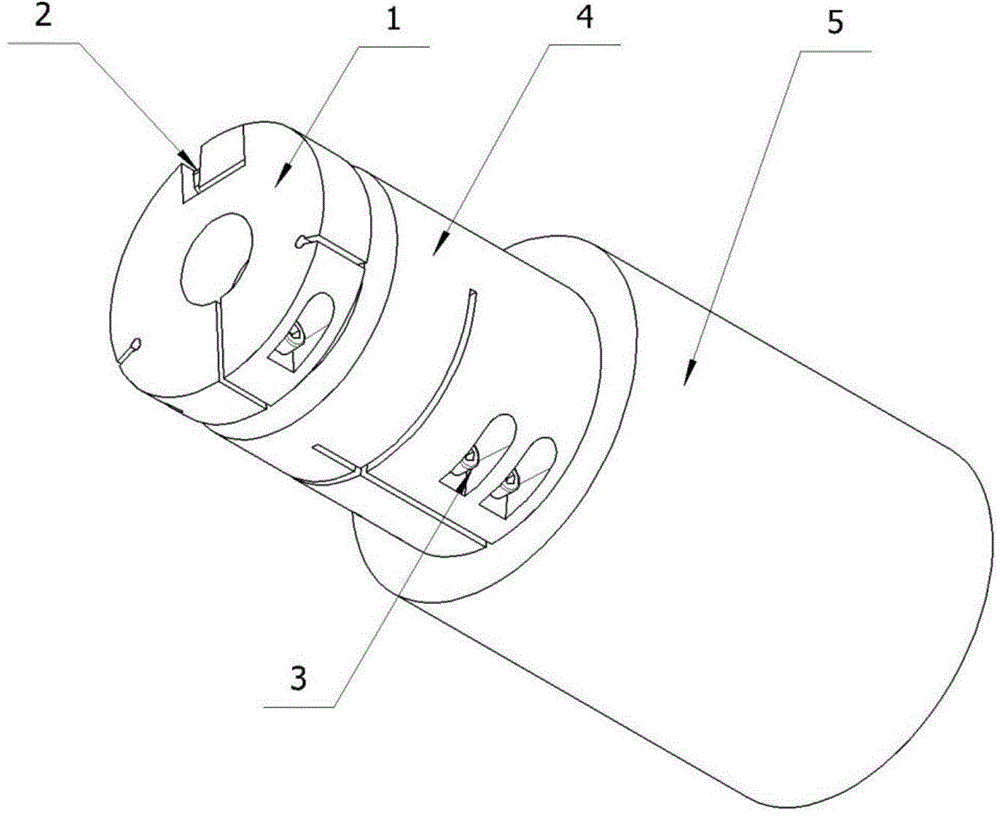
[0029] Generally, the weight of shaft parts is relatively heavy, and it is difficult to overcome the transmission torque. At the same time, the variation of positioning diameter is relatively large. Therefore, a driving device suitable for mass production is required. Aiming at the difficult problems in processing, the present invention proposes a synchronous rotation drive device for shaft parts, such as figure 1 As shown, the device includes a locking flange 1, a gap nut 2, a plurality of compression screws 3 and a drive sleeve 4;

[0030] Its specific structure is:

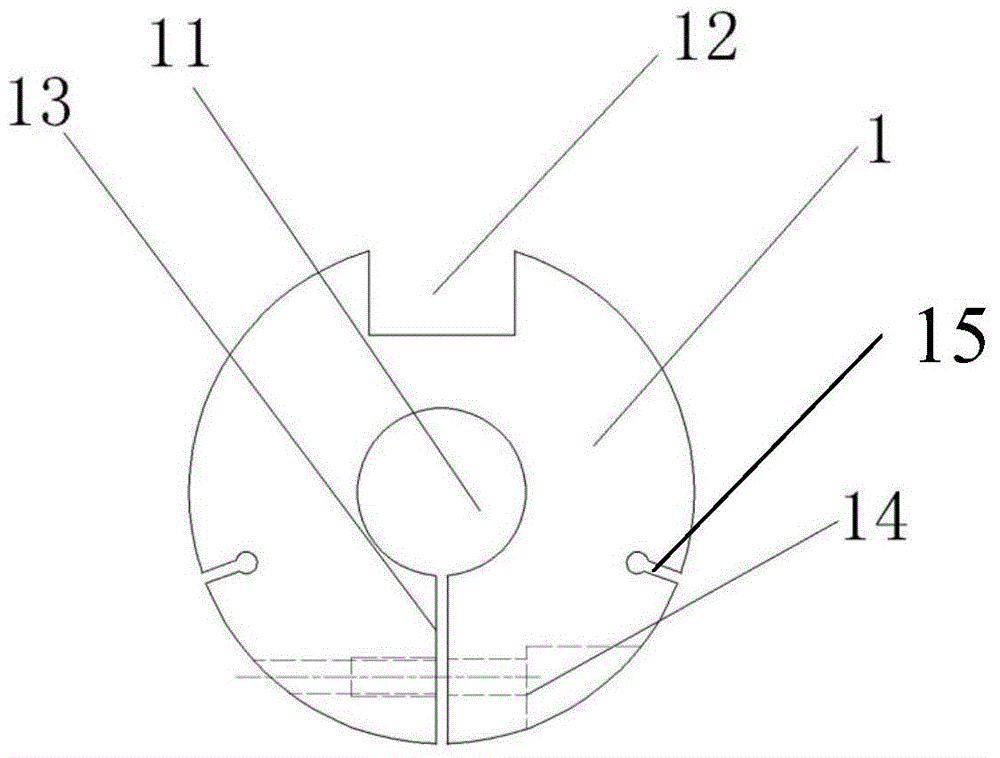
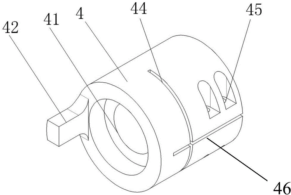
[0031] Such as figure 2 , the locking flange 1 is disc-shaped and has a positioning through hole 11 in the center; the diameter of the positioning through hole 11 is adapted to the outer diameter of the shaft parts to be processed; the locking flange 1 is provided with a groove 12; The locking flange 1 is also provided with a first clearance groove 13 communicating with the positioning through hole 11; the l...


PUM

PropertyMeasurementUnit
Thicknessaaaaaaaaaa
Heightaaaaaaaaaa
Widthaaaaaaaaaa

Abstract

The invention belongs to the technical field of machining and manufacturing, and particularly relates to a synchronous rotation drive device for a shaft part. The synchronous rotation drive device for the shaft part comprises a locking flange, a clearance nut, multiple pressing screws and a drive sleeve. A groove is formed in the locking flange. A protrusion matched with the groove is arranged on the end face of the drive sleeve, and a threaded hole is formed in the protrusion. A nut head of the clearance nut abuts against the side wall of the groove. A threaded rod of the clearance nut is installed in the threaded hole of the protrusion. The pressing screws are used for installing a part to be machined on the locking flange and a machine tool cone vertex. The drive device is easy to machine, convenient to operate, and capable of guaranteeing the shaft part machining accuracy.

Description

technical field [0001] The invention belongs to the technical field of machining and manufacturing, and relates to a drive device, in particular to a synchronous rotation drive device for shaft parts. Background technique [0002] In the grinding of the single keyway of the intermediate shaft of the transmission, the grinding of the rectangular spline of the output shaft and the grinding of the gear part of the sun gear of the reducer, the requirements for the tolerance of the keyway and the inverted bevel tooth after grinding are very strict. In general, the rotation drive of the shaft parts with the two centers as the processing reference adopts the traditional lever and clamp device. [0003] However, due to the traditional driving device, the length of the lever is too long and the rigidity is too poor, the clamping surface of the clamp is small, and under the action of a large grinding force, it is easy to generate torque, resulting in the inability to drive synchronous...

Claims


Application Information

Patent Timeline
IPC IPC(8): B24B47/12
CPCB24B47/12
Inventor 乔茂祁养锋贺冬冬
Owner BAOJI FAST GEAR
Learn More