Power tool

A technology for a power tool and a winding column, which is applied in the field of power tools, can solve the problems of inconvenient use, lack of consideration, and inconvenient machining of workpieces, and achieves the effects of convenient use and low cost.

Active Publication Date: 2015-09-30
POSITEC POWER TOOLS (SUZHOU) CO LTD
View PDF8 Cites 1 Cited by
  • Summary
  • Abstract
  • Description
  • Claims
  • Application Information

AI Technical Summary

Problems solved by technology

[0007] The casing of the power tool includes a casing for housing the motor and a handle set at an angle to the casing. The handle is integrated with the casing, and the handle is fixed relative to the casing. The structure is simple, but the position of the handle under different working conditions of the power tool is not considered. different requirements, it is inconvenient to use, for example, in the working condition with narrow working space, the power tool needs the handle to be far away from the output rod, so as to avoid the handle affecting the feeding of the output rod towards the workpiece; in the working condition of the workpiece is very hard, the power tool needs to The handle is close to the output rod so that the operator can provide greater force for the feed of the output rod to process the workpiece smoothly
Therefore, the above-mentioned new power tool cannot meet the different requirements for the handle position under different working conditions, and the processing of the workpiece is not convenient enough
In addition to the above new power tools, other power tools with a fixed handle relative to the housing have the same problem

Method used


Image

  • Power tool
  • Power tool
  • Power tool

Examples


Embodiment Construction

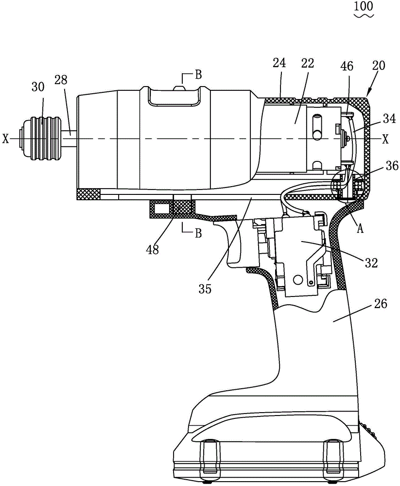
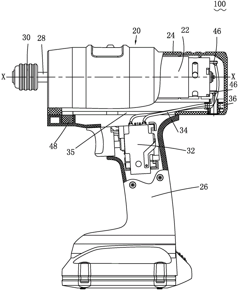
[0036] See figure 1 and figure 2 The power tool 100 of this embodiment includes a casing 20, the casing 20 includes a casing 24 for accommodating the motor 22, and a handle 26 connected to the casing 24. The output shaft of the motor 22 drives the output rod 28 to move through a transmission mechanism. A collet 30 on which a working head (not shown) can be mounted is fixedly connected to the output rod 28 . When the power tool 100 is in use, the motor 22 drives the working head to move through the transmission mechanism, the output rod 28 and the collet 30 to process the workpiece.

[0037] The output shaft of the motor 22 has an axis X-X, and the output rod 28 has a center line. In this embodiment, the axis X-X of the output shaft of the motor 22 coincides with the center line of the output rod 28, so that the power tool 100 has a compact structure.

[0038] The handle 26 and the casing 24 are slidably coupled along the extension direction of the axis X-X of the output sha...


PUM


Abstract

The invention provides a power tool. The power tool comprises a shell. The shell comprises a machine shell used for containing a motor and a handle which is connected with the machine shell. An output shaft of the motor drives an output rod to move through a transmission mechanism. The output shaft is provided with an axis. The handle and the machine shell are in sliding fit connection in the extending direction of the axis. The handle is provided with a control piece. The control piece and the motor are electrically connected through a wire. The shell is provided with a winding device. The winding device tensions the wire in the winding direction of the tensioned wire. The wire can be effectively arranged, and it is avoided that sliding of the handle relative to the machine shell is affected due to the disordered wire.

Description

technical field [0001] The invention relates to a power tool, in particular to a power tool with a handle that can move relative to a casing. Background technique [0002] Commonly used power tools include power tools that output rotary motion at the output end, such as electric drills, screwdrivers, etc.; and power tools that output reciprocating motion at the output end, such as reciprocating saws, jig saws, and the like. [0003] Existing power tools usually can only output one kind of motion at the output end. For example, electric drills can only output rotary motion; reciprocating saws can only output reciprocating motion; however, operators often need to use To many different power tools, purchasing these different power tools individually can increase the burden on the consumer. [0004] For this reason, different power tool adapters have appeared in the prior art to expand the use range of power tools, such as the reciprocating adapter provided for electric drills,...

Claims


Application Information

Patent Timeline
Patent Type & Authority Applications(China)
IPC IPC(8): B25F5/02
CPCB25F5/02B25F5/021
Inventor 顾育明
Owner POSITEC POWER TOOLS (SUZHOU) CO LTD
Why Eureka
Try Eureka