a bridge stone cutter

A stone cutter and bridge-type technology, applied in the direction of stone processing tools, stone processing equipment, work accessories, etc., can solve the problem that dust cannot be completely blocked, and achieve the effect of novel structure, ingenious design, and simple structure

Active Publication Date: 2019-02-22
福建省南安市巨轮机械有限公司
View PDF10 Cites 0 Cited by
  • Summary
  • Abstract
  • Description
  • Claims
  • Application Information

AI Technical Summary

Problems solved by technology

[0003] The present invention provides a bridge-type stone cutter, the main purpose of which is to overcome the problem that the existing bridge-type stone cutter cannot completely prevent dust and water from entering the ram

Method used


Image

  • a bridge stone cutter
  • a bridge stone cutter
  • a bridge stone cutter

Examples


Embodiment Construction

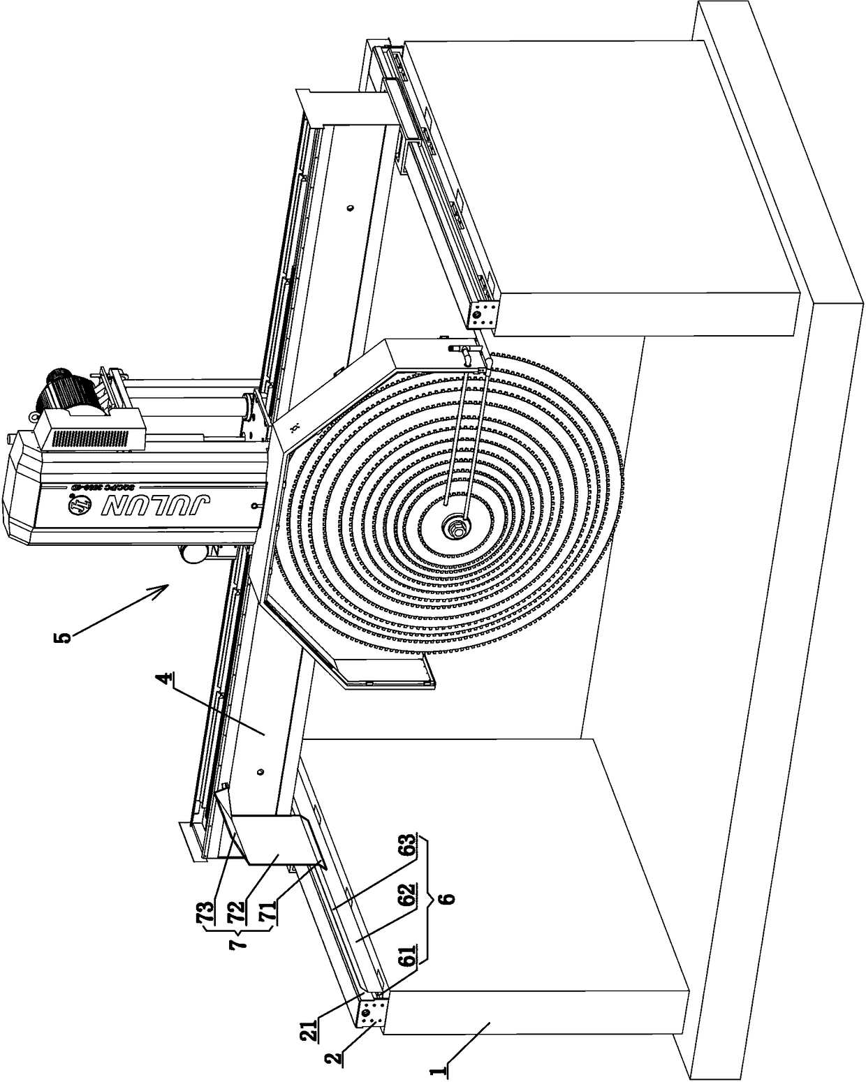
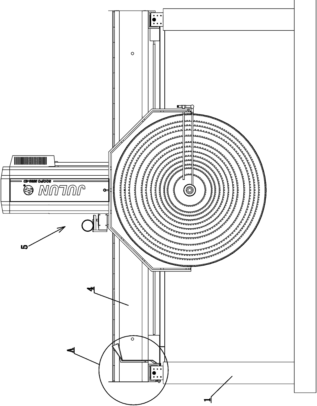
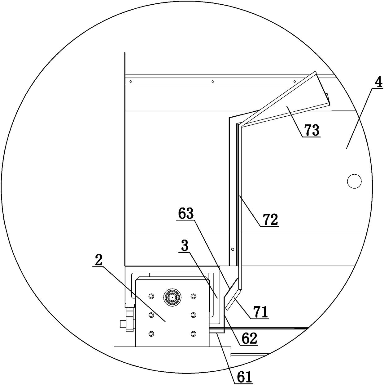
[0017] refer to Figure 1 to Figure 3 . A bridge-type stone cutter, comprising a base 1, a side beam 2 arranged on the base 1, a side beam ram 3 arranged on the side beam 2, a beam 4 connected to the side beam ram 3, and a 4 on the host device 5 . The top of the side beam 2 is covered with a side beam shield 21 along its length direction; A second water retaining bucket 7 is provided, and the second water retaining bucket 7 is located inside the first water retaining bucket 6 . The first water retaining bucket 6 includes a first horizontal plate 61 , a first vertical plate 62 and a first inclined plate 63 , one end of the first horizontal plate 61 is fixedly connected to the inner surface of the side beam 2 , and the first horizontal plate The other end of the plate 61 is fixedly connected to the bottom end of the first vertical plate 62 , and the top end of the first vertical plate 62 is fixedly connected to the bottom end of the first inclined plate 63 . The lower part o...


PUM


Abstract

The invention discloses a novel bridge type stone cutting machine. The novel bridge type stone cutting machine comprises a base, edge beams arranged on the base, edge beam rams which are respectively arranged on the edge beams, a transverse beam connected with the edge beam rams, and a host device arranged on the transverse beam, wherein an edge beam protection hood covers the top of each edge beam along the length direction of the edge beam; a first water retaining hopper is arranged on the inner side of each edge beam along the length direction of the edge beam; a second water retaining hopper is located on the front end surface of the transverse beam, and is located on the inner side of the corresponding first water retaining hopper; each first water retaining hopper comprises a first transverse plate, a first vertical plate, and a first oblique plate; one end of each first transverse plate is fixedly connected with the inner side surface of the corresponding edge beam; the other end of each first transverse plate is fixedly connected with the bottom end of the corresponding first vertical plate; the top end of each first vertical plate is fixedly connected with the bottom end of the corresponding first oblique plate; the lower part of each edge beam ram is located in the space enclosed by the corresponding first transverse plate and the corresponding first vertical plate; the bottom of the second water retaining hopper is located on the right side of the corresponding first vertical plate; and the height of the second water retaining hopper is higher than that of the corresponding edge beam ram.

Description

technical field [0001] The invention relates to the field of stone cutters, in particular to a bridge-type stone cutter. Background technique [0002] Bridge stone cutter is widely used in construction, decoration and other industries, and it is suitable for cutting all kinds of stone, building materials, granite, marble and so on. The patent document with the patent number of 2012207334404 discloses a side beam ram of a bridge stone cutter, which includes a ram body movable on a V-shaped track of the side beam. The bottom of the ram body is formed with a first dust protection edge extending downward from the inner side of the side beam and opposite to the inner side, the bottom of the ram body is formed to extend downward from the outer side of the side beam and The second dust-proof protective edge opposite to the outer edge, the side beam and the side beam ram are labyrinth seals. The first dust-proof guard is used to block a large amount of dust and splashed water gene...

Claims


Application Information

Patent Timeline
Patent Type & Authority Patents(China)
IPC IPC(8): B28D1/04B28D7/00B28D7/02
CPCB28D1/044B28D7/00B28D7/02
Inventor 郑远东陈新刚
Owner 福建省南安市巨轮机械有限公司
Why Eureka
Try Eureka