Check patentability & draft patents in minutes with Patsnap Eureka AI!

A robot lifting device and lifting method

A lifting device and robot technology, applied in the direction of manipulators, program-controlled manipulators, claw arms, etc., can solve problems such as difficult to ensure the stability of the lifting mechanism, reduce the size of the design, reduce energy consumption of mobile robots, etc., to achieve convenient drive control and appropriate size , Increase the effect of body stability

Active Publication Date: 2016-06-29
YIJIAHE TECH CO LTD
View PDF7 Cites 1 Cited by
  • Summary
  • Abstract
  • Description
  • Claims
  • Application Information

AI Technical Summary

Problems solved by technology

This solution is not suitable for application scenarios where continuous lifting is controlled by a central controller, and it is difficult to ensure the stability of the lifting mechanism when the load is heavy
[0004] Chinese Invention Patent Document CN104218486A "A Cleaning Device for Substation Insulation Columns" discloses a 3-level driven lifting mechanism, each level of the lifting mechanism consists of a screw and a driving device, and the sliding sleeves are used to connect between the levels. This device requires many motor drives, adversely affecting the energy-efficient and compact design of mobile robots that rely on battery power

Method used


Image

  • A robot lifting device and lifting method
  • A robot lifting device and lifting method
  • A robot lifting device and lifting method

Examples


Embodiment Construction

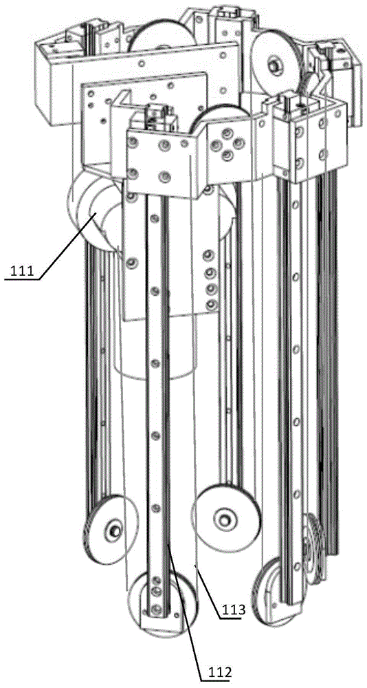
[0025] Such as figure 1 , 2 As shown, the fuselage 101 is located between the suspension mechanism 102 and the measuring equipment 104 , and the suspension mechanism loads the fuselage 101 and the measuring equipment 104 to travel along the guide rail 103 . The fuselage 101 includes a fuselage sliding arm system, a motor drive mechanism 111 , a fuselage shell 110 , and a pair of head and tail drawstrings 113 . The fuselage shell 110 covers the fuselage sliding arm system.

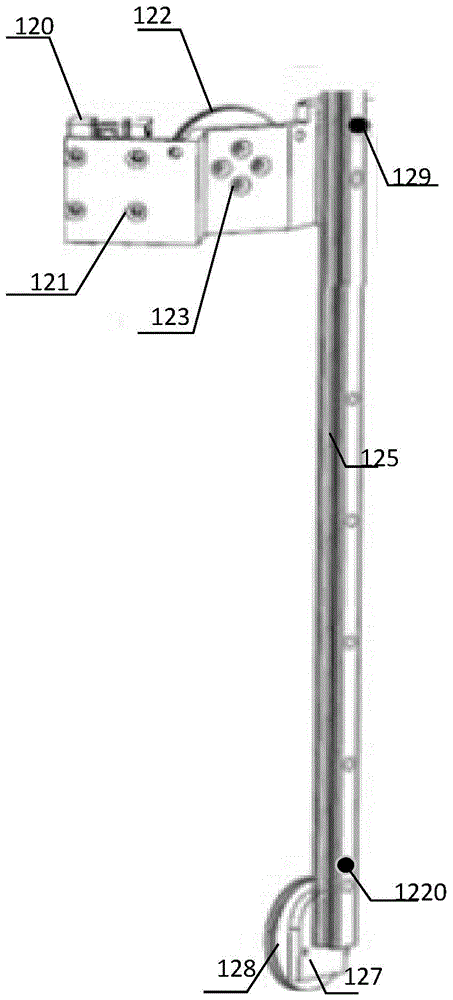
[0026] Such as image 3 As shown, the fuselage sliding arm system includes several stages of sliding arms (sliding arm one 134, sliding arm two 135, sliding arm three 136, sliding arm four 137) and a second guide rail 133, the lower end of the second guide rail 133 is installed with a second The lower pulley 126 can also install the lower pulley connection block at the lower end of the second guide rail 133, and the second lower pulley is installed on the lower pulley connection block; the upper end of t...


PUM


Abstract

The invention provides a robot lifting device which comprises a hanging mechanism, a body and sliding arm system, a motor driving mechanism, a head pulling rope and a tail pulling rope, wherein the body and sliding arm system comprises a plurality of sliding arms and a second guide rail; a second lower pulley is mounted at the lower end of the second guide rail; the upper end of the second guide rail is mounted on the hanging mechanism; the motor driving mechanism is mounted on the second guide rail or the hanging mechanism; the sliding arms comprise guide rails, lower pulleys, front guide rail connecting slide blocks and upper pulleys; the upper pulleys and the lower pulleys are respectively mounted at the upper ends and the lower ends of the guide rails; the front guide rail connecting slide blocks are mounted on the side surfaces of the upper ends of the guide rails; each front guide rail connecting slide block of each sliding arm in the lower stage of the multiple sliding arms is slidingly mounted on each guide rail of each sliding arm in the upper stage; and the front guide rail connecting slide block of the first sliding arm of the multiple sliding arms is slidingly mounted on the second guide rail. With the adoption of the working principle of the pulleys, continuous lifting of a robot within the full range can be realized only by adopting the single motor driving mechanism, integral miniaturization of the robot is facilitated, and the total energy consumption is reduced.

Description

technical field [0001] The invention belongs to the technical field of robot lifting equipment, and relates to a robot lifting device and a lifting method. Background technique [0002] Lifting mechanisms are widely used in construction machinery. The lifting mechanisms of heavy machinery are generally bulky and difficult to control with high precision, so it is difficult to be widely used in the design of small and medium-sized robots. [0003] Chinese invention patent document CN102235840A "A Lifting System for Target Lifting Robot" describes a lifting system using spring control materials. The positioning method is switch positioning, and the pushing rod and relay post interact to complete the lifting function. This device is suitable for shooting targets In the application scenario where the target is either raised or retracted during the process, the target is lighter and the spring tube materials nested inside each other can meet the corresponding needs. This solution...

Claims


Application Information

Patent Timeline
Patent Type & Authority Patents(China)
IPC IPC(8): B25J18/02B25J9/00
Inventor 许春山兰新力
Owner YIJIAHE TECH CO LTD
Features
  • R&D
  • Intellectual Property
  • Life Sciences
  • Materials
  • Tech Scout
  • Unparalleled Data Quality
  • Higher Quality Content
  • 60% Fewer Hallucinations
Learn More