Floor Drain Core and Its Odor-proof Floor Drain
A floor drain and inner core technology, which is applied in waterway systems, drainage structures, water supply devices, etc., can solve the problems of inability to deodorize, floor drains are easy to slip, and difficult to disassemble, and achieve the effect of easy daily cleaning, good deodorization effect, and convenient disassembly
- Summary
- Abstract
- Description
- Claims
- Application Information
AI Technical Summary
Problems solved by technology
Method used
Image

Examples
Embodiment 1
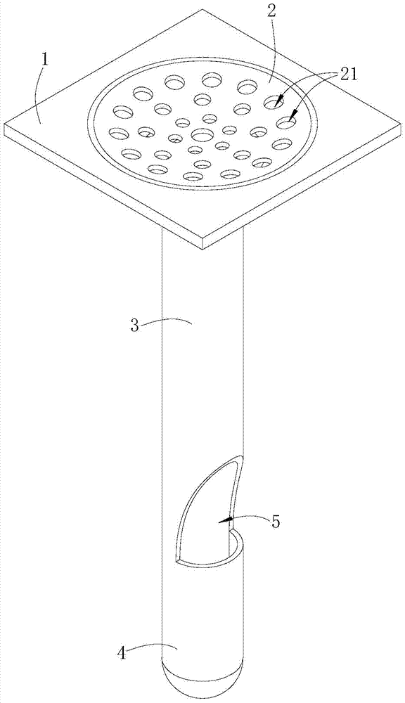
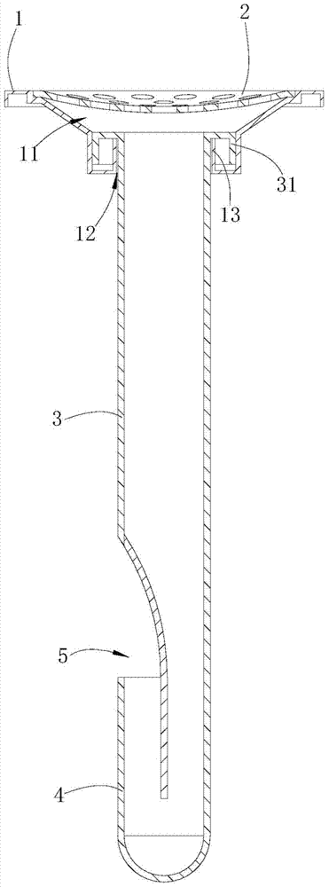
[0039] Such as Figures 1 to 2 shown
[0040] The deodorant floor drain includes a panel 1 and a cover plate 2. There is a drainage groove 11 formed by a depression on the upper surface of the panel 1. There is a drainage hole 12 at the bottom of the drainage groove 11. A shoulder 13 extends upward from the edge of the drainage hole 12. The cover plate 2 is arranged on The upper part of the drainage groove 11 of the panel 1, the upper end surface of the cover plate 2 has a spherical depression, and the cover plate 2 has a plurality of through holes 21;
[0041] The drain hole 12 of the panel 1 is provided with a floor drain inner core, which includes a catheter 3 and a liquid seal 4. The catheter 3 and the liquid seal 4 of the floor drain inner core are of an integrated structure. There is an outer convex ring 31 extending outward, and the outer convex ring 31 cooperates with the shoulder 13 of the panel 1 so that the upper end of the catheter 3 completely covers the drain ho...
Embodiment 2
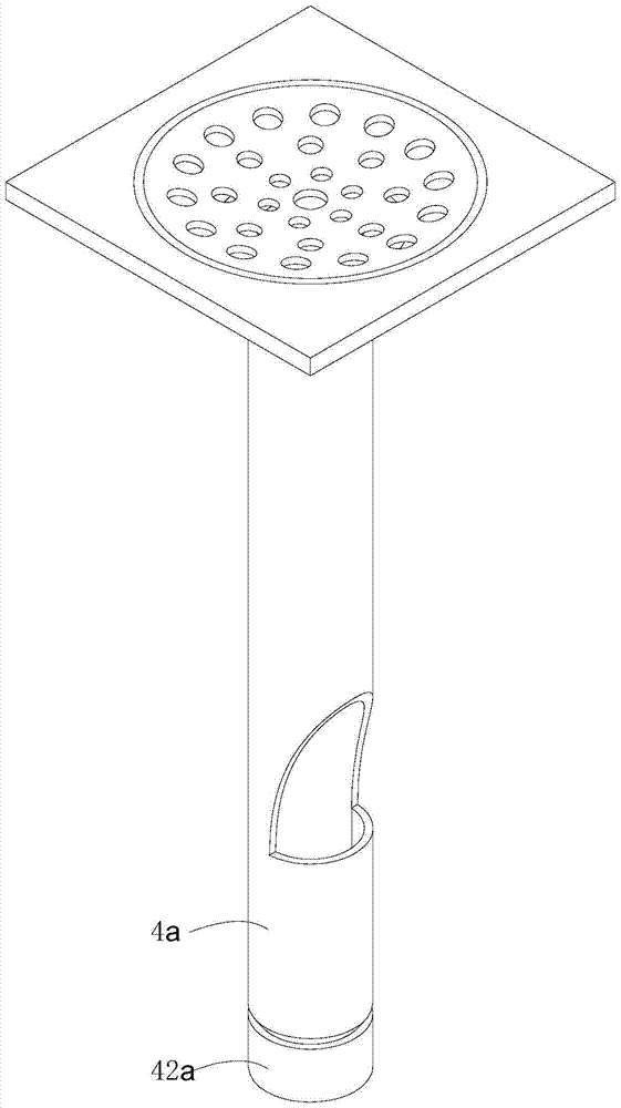
[0043] Such as Figures 3 to 4 shown
[0044] The difference between this embodiment and the first embodiment is that there is a dredging hole 41a at the bottom of the liquid seal portion 4a, and a screw cap 42a is provided outside the dredging hole 41a, and the screw cap 42a is screwed to the side wall of the liquid seal portion 4a.
Embodiment 3
[0046] Such as Figures 5 to 6 shown
[0047] The deodorant floor drain includes a panel 1b and a cover plate 2b. There is a drainage groove 11b formed by a depression on the upper surface of the panel 1b. There is a drain hole 12b at the bottom of the drain groove 11b. A shoulder 13b extends upward from the edge of the drain hole 12b. The cover plate 2b is arranged on The upper part of the drainage groove 11b of the panel 1b, the upper end surface of the cover plate 2b has a spherical depression, and the cover plate 2b has a plurality of through holes 21b;
[0048] The drain hole 12b of the panel 1b is provided with a floor drain inner core. The floor drain inner core includes a catheter 3b and a liquid seal 4b. The catheter 3b and the liquid seal 4b of the floor drain inner core are separate structures. An outer convex ring 31a extends outward, and the outer convex ring 31a cooperates with the shoulder 13b of the panel 1b so that the upper end of the catheter 3b completely ...
PUM
 Abstract
Description
Claims
Application Information
 - R&D
- Intellectual Property
- Life Sciences
- Materials
- Tech Scout
- Unparalleled Data Quality
- Higher Quality Content
- 60% Fewer Hallucinations
Browse by: Latest US Patents, China's latest patents, Technical Efficacy Thesaurus, Application Domain, Technology Topic, Popular Technical Reports.
© 2025 PatSnap. All rights reserved.Legal|Privacy policy|Modern Slavery Act Transparency Statement|Sitemap|About US| Contact US: help@patsnap.com