
A load conversion method for hydraulic lifting equipment replacement

A technology of hydraulic lifting and switching methods, applied in the processing of building materials, preparation of building components on site, pillars, etc., can solve problems such as high safety risks, and achieve the effect of safe load switching

Active Publication Date: 2017-04-19
SHANGHAI BAOYE GRP CORP
View PDF5 Cites 0 Cited by
  • Summary
  • Abstract
  • Description
  • Claims
  • Application Information

AI Technical Summary

Problems solved by technology

The force on the steel strand is very large, and the roof structure has a certain deformation (deflection) at the support point. It is very dangerous to transfer the load to a single support suddenly; in addition, the load is unloaded by the faulty lifting cylinder Forcibly transferred to the support tower, the safety risk of unloading operation when the lifting cylinder fails or the steel strand is broken is very high

Method used


Image

  • A load conversion method for hydraulic lifting equipment replacement

Examples


Embodiment Construction

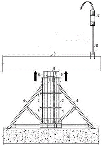
[0013] Such as figure 1 As shown, in the present invention, when the steel structure roof 9 is in the hydraulic lifting construction process, the failure of the lifting cylinder 7 cannot be ruled out and must be replaced or the lifting steel strand 8 is broken, the load conversion method of the present invention will be used to lift the lifting mechanism. The load can be safely and reliably transferred to the temporary support load transfer device, the specific steps are as follows:

[0014] The technical personnel issue the equipment replacement plan, and determine the specifications and sizes of the components of the temporary support load conversion device of the present invention through calculation and analysis, and use ANSYS for finite element analysis of complex nodes;

[0015] The type of hydraulic jack 5 is determined: the tonnage of the jack 5 is determined according to the reaction force value of the temporary support point; according to the deformation difference Δ...


PUM


Abstract

The invention relates to device lifting, in particular to a load lifting method of a hydraulic lifting device. According to the method, as three temporary supports are additionally arranged at lower chord joints of a roof structure, the roof structure is directly supported through the support in the middle, and two hydraulic jacks are installed at the tops of the supports on the two sides, the load on a failing lifting mechanism is safely and reliably transferred to a temporary supporting device; meanwhile, after device replacement is completed, the load is retransferred to the lifting mechanism. By means of the method, it is guaranteed that device replacement and load transferring are safely and smoothly completed in the whole process.

Description

technical field [0001] The invention relates to equipment lifting, in particular to a method for hydraulic lifting equipment to lift loads. Background technique [0002] During the hydraulic lifting construction process, when the hydraulic lifting equipment fails, the conventional method is to directly add a single support under the structure, and unload by cutting the steel strands one by one. The force on the steel strand is very large, and the roof structure has a certain deformation (deflection) at the support point. It is very dangerous to transfer the load to a single support suddenly; the other is to unload the load through the faulty lifting cylinder. Forcibly transferred to the support tower, the unloading operation when the lifting cylinder fails or the steel strand is broken is very risky. Contents of the invention [0003] The present invention aims to solve the above-mentioned defects of the prior art, and provides a load conversion method for hydraulic lifti...

Claims


Application Information

Patent Timeline
Patent Type & Authority Patents(China)
IPC IPC(8): E04G25/00E04G21/14
Inventor 陈辉张海礁蒋国明邱顶宏李旻张福川
Owner SHANGHAI BAOYE GRP CORP
Learn More