Control system and control method for multi-station rotary flocking

A control system and multi-station technology, applied in the control of multi-station rotary hair planting, the control system of multi-station rotary hair planting, and the field of control systems, can solve the interference between the hair-planting nozzle and the brush plate, the large size and weight of the hair-planting machine, Problems such as space occupation above the drilling and planting table

Pending Publication Date: 2019-02-22
YANGZHOU HAIXING CNC BRUSH MACHINERY
View PDF1 Cites 0 Cited by
  • Summary
  • Abstract
  • Description
  • Claims
  • Application Information

AI Technical Summary

Problems solved by technology

[0003] When the plane brush is relatively long, the machine head needs to protrude forward for a relatively long distance due to the wide drilling and planting workbench. The cantilever structure leads to a large volume and weight of the overall tufting machine, and the space above the drilling and planting workbench is drilled. Mechanism and tufting mechanism are occupied, and automatic loading and unloading devices cannot be arranged. The loading and unloading of brush boards are all completed by manual assistance, which is labor-intensive and has certain risks.
Once the operator makes a mistake, such as failing to remove the brush plate that has been planted in time, it will cause interference between the planting nozzle and the brush plate, resulting in equipment damage

Method used


Image

  • Control system and control method for multi-station rotary flocking
  • Control system and control method for multi-station rotary flocking
  • Control system and control method for multi-station rotary flocking

Examples


Embodiment Construction

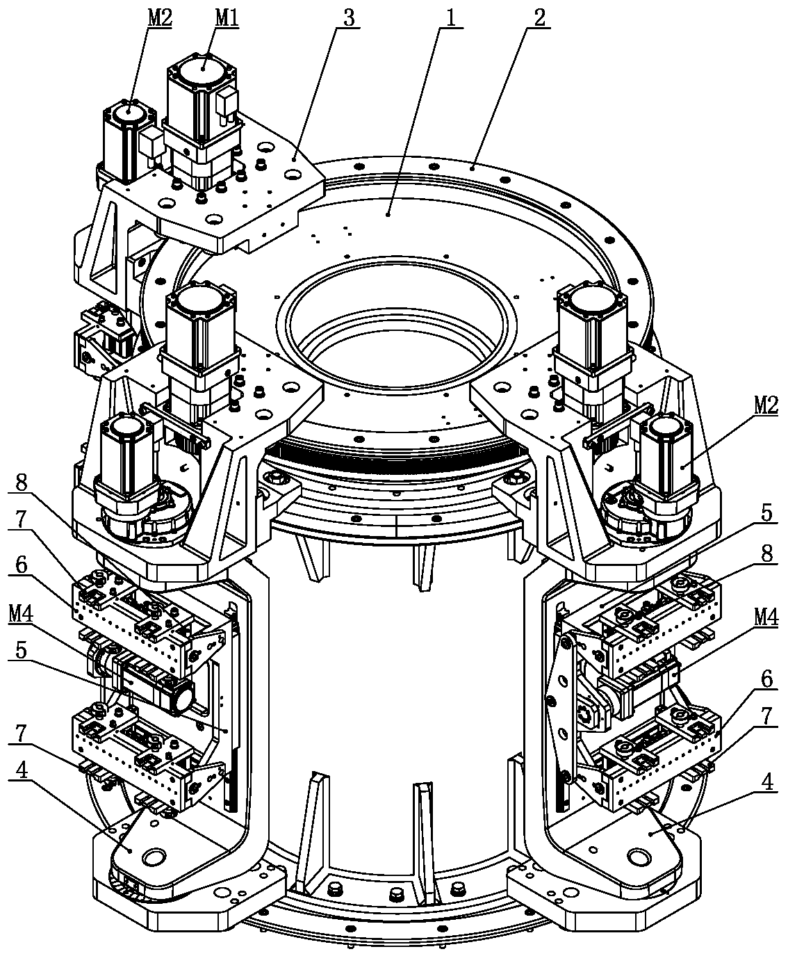
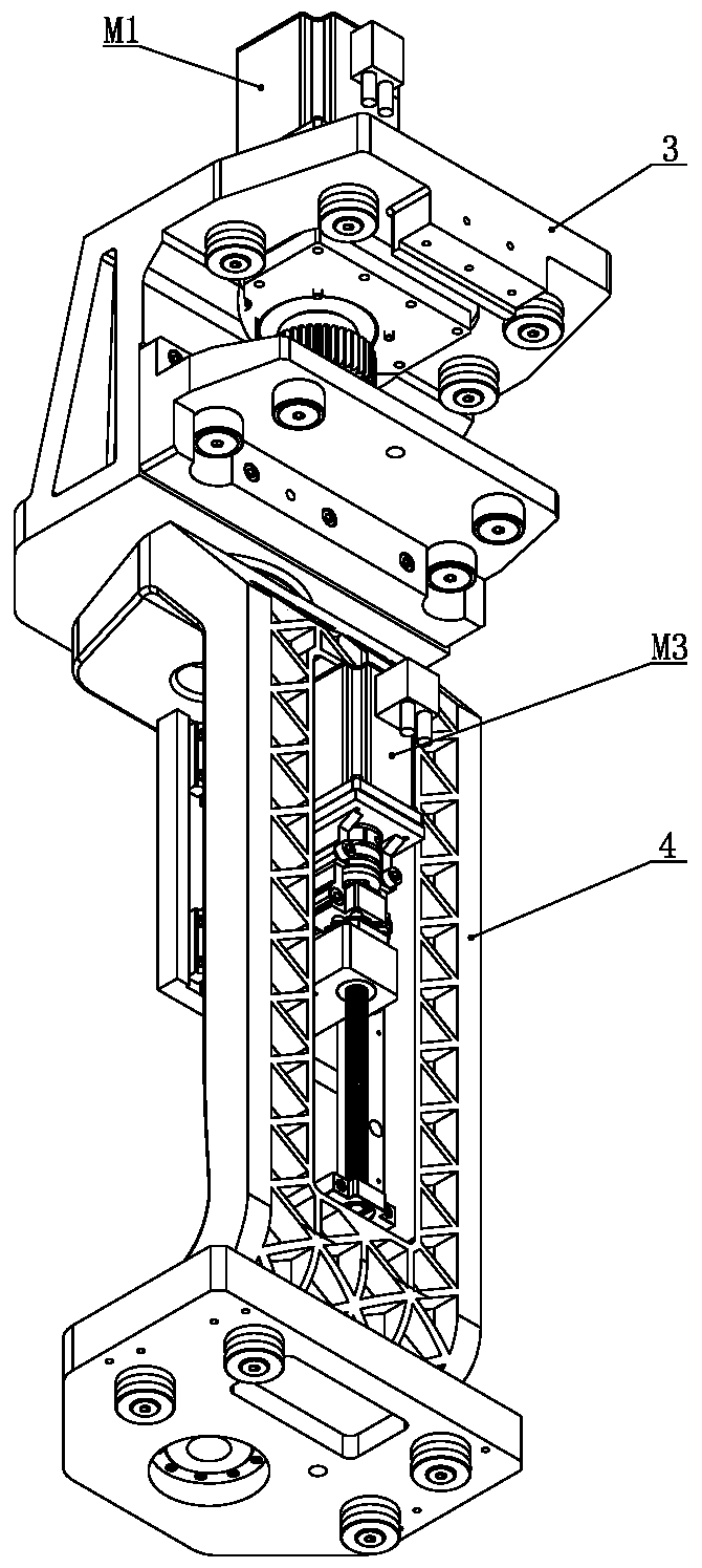
[0028] Such as figure 1 , figure 2 As shown, the multi-station rotary tufting machine in the present invention comprises a workbench central cylinder 1, an annular guide rail 2 is installed on the outer periphery of the workbench central cylinder 1, and a loading and unloading station and a drilling station are arranged on the circumference of the annular guide rail 2. And the tufting station, each station is equipped with a station turntable 3 respectively, and each station turntable 3 is equipped with a rotatable workbench support plate 4 respectively, and each workbench support plate 4 is respectively equipped with a liftable The brush body workbench 5 and the brush body workbench 5 are respectively equipped with swingable brush body mounting plates 6 , and the upper and lower sides of each brush body mounting plate 6 are respectively provided with jaws 7 .

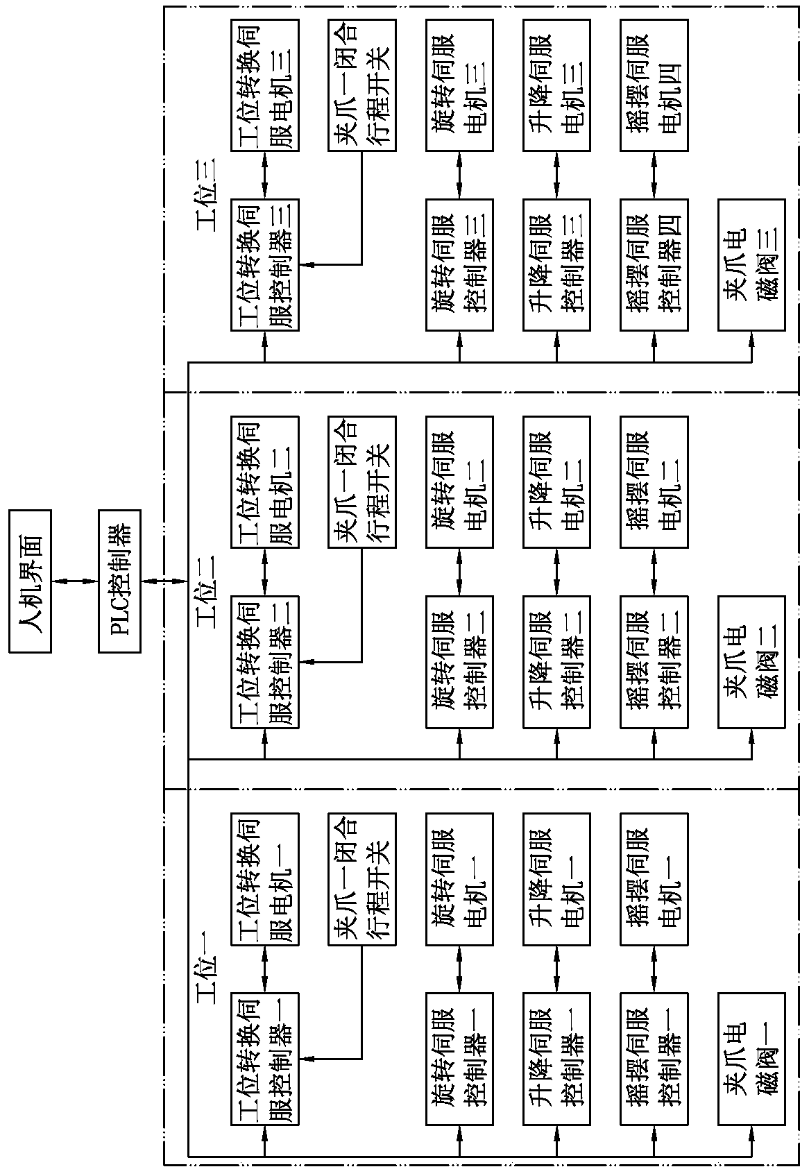
[0029] Such as Figure 3 to Figure 8 As shown, in the control system of multi-station rotary tufting of the prese...


PUM


Abstract

The invention discloses a control system and a control method for multi-station rotary flocking, wherein each station rotary frame is driven by a station conversion servo motor controlled by a stationconversion servo driver, a workbench support plate is driven by a rotary servo motor controlled by a rotary servo driver, a brush body workbench is driven by a lifting servo motor controlled by a lifting servo driver, each clamping jaw is driven by a clamping jaw cylinder controlled by a clamping jaw electromagnetic valve, each brush body mounting plate is driven by a swing servo motor controlledby a swing servo driver, each servo driver is controlled by a PLC controller, which is connected with a human-computer interface. The flocking process achieved flocking comprises the following stepsin sequence: the station rotary frame arrives at a flocking station, the workbench support plate rotates to finish a row of flocking, the brush body workbench ascends and descends to finish each row of flocking, the brush body workbench walks to a feeding and discharging station for blanking and feeding, and walks to a drilling station for drilling, and walks to the flocking station again. The control system and the control method for multi-station rotary flocking have high automation degree and high production efficiency.

Description

technical field [0001] The invention relates to a control system of a wool planting machine, in particular to a control system for multi-station rotary hair planting; the invention also relates to a control method for multi-station rotary hair planting, which belongs to the technical field of industrial automation control. Background technique [0002] For the processing of flat brushes, the drilling and planting worktable of the traditional tufting machine is located below, the brush plate of the flat brush is clamped on the drilling and planting workbench, and the length direction of the flat brush brush plate extends along the width direction of the drilling and planting workbench , the drilling and hair-planting surface of the flat brush board is facing upwards, the machine head is located above the drilling and planting workbench, the machine head is equipped with a drilling mechanism and a hair-planting mechanism, the rear side of the machine head is connected to the ma...

Claims


Application Information

Patent Timeline
IPC IPC(8): A46D3/06A46D3/08G05B19/05
CPCA46D3/062A46D3/08A46D3/085A46D3/087G05B19/05
Inventor 王勇
Owner YANGZHOU HAIXING CNC BRUSH MACHINERY
Why Eureka
Try Eureka