
Shaft seal

一种轴密封、密封元件的技术,应用在发动机的密封、机械设备、发动机元件等方向,能够解决部件数量增多、密封元件共同旋转、产品单价变高等问题

Active Publication Date: 2015-09-30
MITSUBISHI CABLE IND LTD
View PDF8 Cites 4 Cited by
  • Summary
  • Abstract
  • Description
  • Claims
  • Application Information

AI Technical Summary

Problems solved by technology

[0003] However, when the gasket is provided, the number of parts increases, the assembly work takes a lot of time, and the unit price of the product becomes higher
Furthermore, when the gasket is omitted, the sealing elements may co-rotate (in the case of rotary motion) as well as fall out (in the case of reciprocating motion)

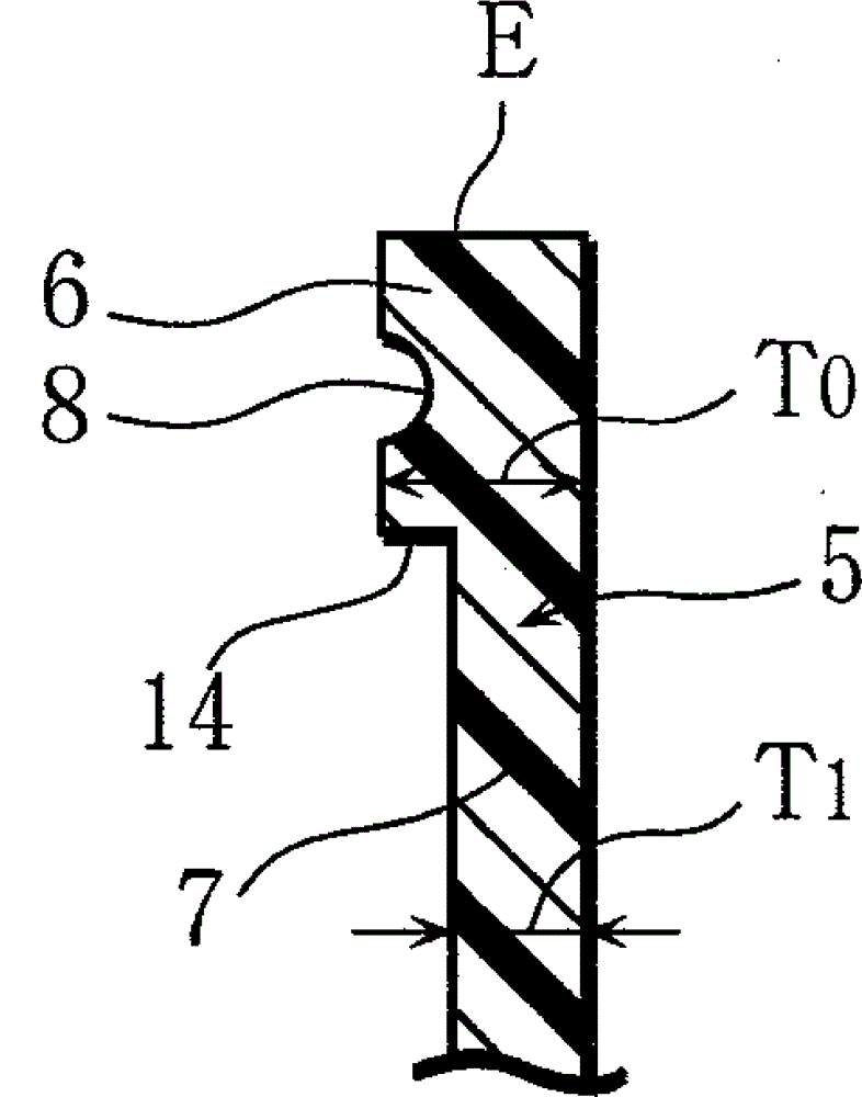
Method used


Image

  • Shaft seal
  • Shaft seal
  • Shaft seal

Examples


Embodiment Construction

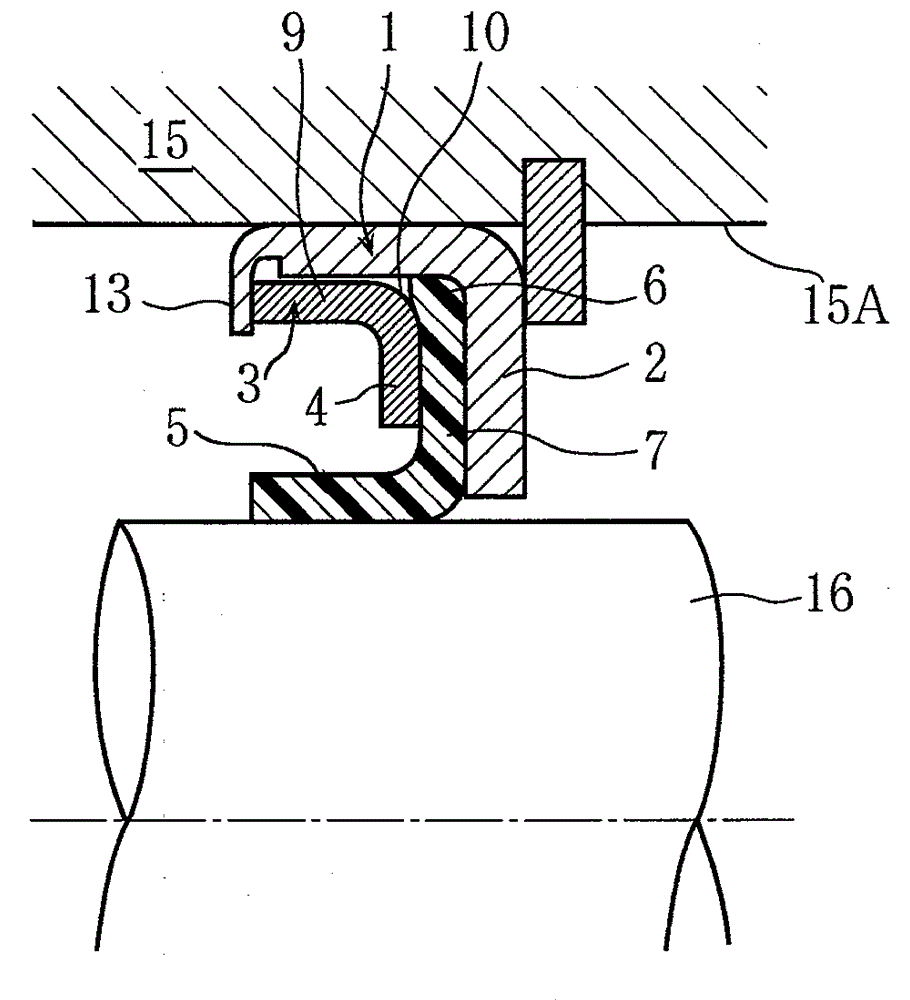
[0013] Preferred embodiments of the present invention will now be described with reference to the accompanying drawings.

[0014] Figure 1 to Figure 3 A first embodiment of the invention is shown. The shaft sealing device is used, for example, in EGR-V, vacuum pump, compressor, (oil pressure or pneumatic) reciprocating cylinder (not shown in the figure). In addition, shaft seals are available for rotary as well as reciprocating motion.

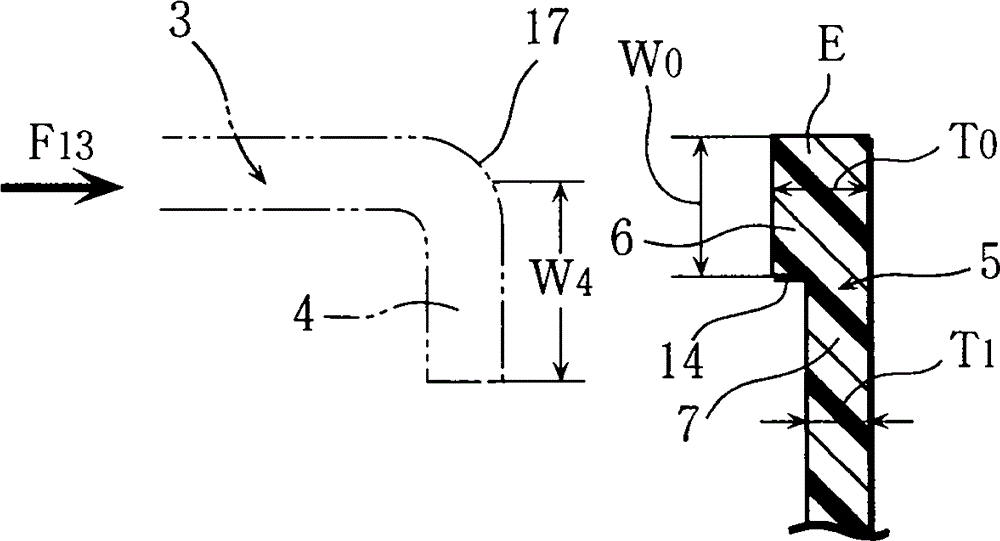
[0015] This shaft seal device is attached to a cylindrical space portion between a circular hole portion 15A of a housing 15 and a shaft 16, and is provided with a sealing member 5 formed of resin adjacent to the shaft 16 (such as figure 1 shown in ). The thickness dimension T of the outer peripheral edge 6 of the sealing member 5 formed of a resin such as PTFE held by the inner peripheral wall portion 2 of the outer case 1 formed of metal and the inner peripheral wall portion 4 of the inner case 3 formed of metal 0 set to image 3 great...


PUM


Abstract

A thickness dimension (T 0 ) of a peripheral edge (6) of a seal element (5) held by an inner brim wall portion (2) of an outer case (1) and an inner brim wall portion (4) of an inner case (3) is set to be larger than a thickness dimension (T 1 ) of a remaining portion (7) of the seal element (5), and a ring concave groove (8) is formed on the peripheral edge (6).

Description

technical field [0001] The present invention relates to shaft seals for sealing rotating and reciprocating shafts. Background technique [0002] As a conventional shaft seal device, there is a shaft seal device in which a seal member and a gasket are fitted between an outer case and an inner case (for example, refer to Japanese Provisional Publication No. 2008-69909 and No. 2009-103264). [0003] However, when the gasket is provided, the number of parts increases, the assembly work takes a lot of time, and the unit price of the product becomes high. Furthermore, when the gasket is omitted, the sealing elements may co-rotate (in the case of rotary motion) as well as fall out (in the case of reciprocating motion). Contents of the invention [0004] It is therefore an object of the present invention to provide a shaft seal which can be manufactured at low cost and by which co-rotation and falling of the sealing elements can be prevented. [0005] According to one aspect of ...

Claims


Application Information

Patent Timeline
Patent Type & Authority Applications(China)
IPC IPC(8): F16J15/32F16J15/3228
CPCF16J15/3268F16J15/3228F16J15/322
Inventor 藤井伸和
Owner MITSUBISHI CABLE IND LTD
Learn More