Laminated spiral type solid-liquid separator with vertical spiral shafts

A solid-liquid separator and screw shaft technology, applied in the direction of presses, manufacturing tools, etc., can solve the problems of inability to accumulate pressure, the dehydrator occupies a large area, and cannot continue to move forward, and achieves simple and convenient structure and operation, and easy to observe. and maintenance, improve the effect of space utilization

Pending Publication Date: 2021-11-02
陕西顺展云康专用汽车有限公司
View PDF4 Cites 0 Cited by
  • Summary
  • Abstract
  • Description
  • Claims
  • Application Information

AI Technical Summary

Problems solved by technology

However, this technical scheme that adopts the design of screw shafts side by side (horizontally arranged) also has the following disadvantages: 1. Since the screw shaft and the feed box are not sealed, continuous positive pressure cannot be generated, and when the material in the cavity advances If the resistance is too large, the subsequent material will advance slowly or even cannot continue to advance, resulting in the inability to increase the processing capacity of the material, the inability to store pressure in the cavity to reduce the moisture content, and even cause the material to block in the cavity
2. The side-by-side design of the screw shafts makes the floor area of ​​the dehydrator larger
3. There are fewer water passages on both sides of the filter chamber, and the water filtration is not smooth enough
4. The lateral sides of the closed ring are wider, and the supporting force is weaker, which may easily cause deformation or even breakage of the closed ring

Method used


Image

  • Laminated spiral type solid-liquid separator with vertical spiral shafts
  • Laminated spiral type solid-liquid separator with vertical spiral shafts
  • Laminated spiral type solid-liquid separator with vertical spiral shafts

Examples


no. 1 example

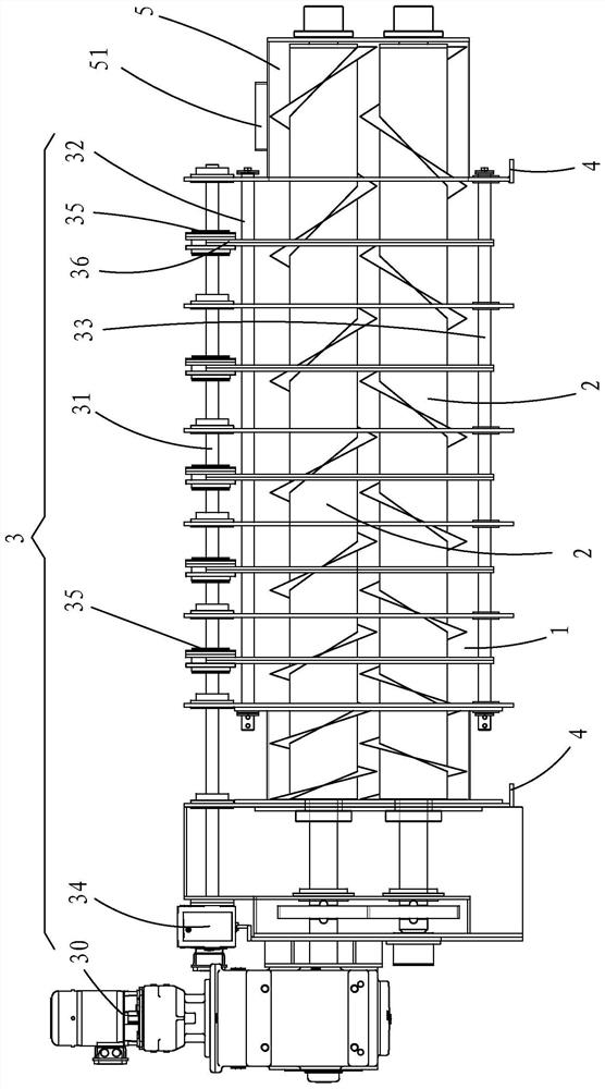
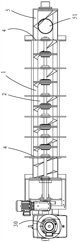
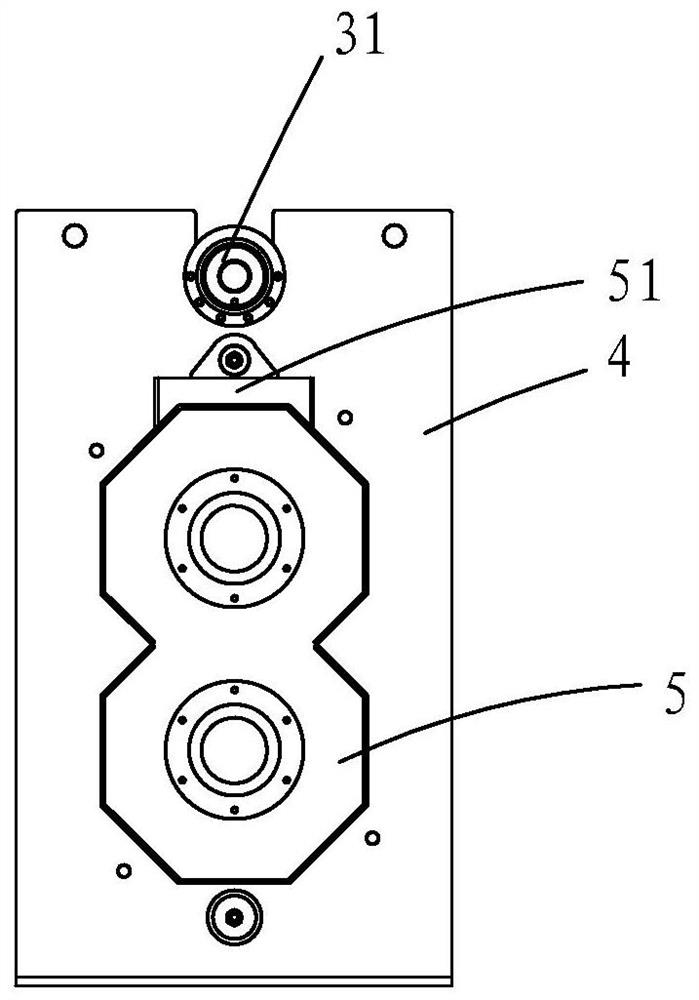
[0051] Such as Figure 1 to Figure 11 As shown, a laminated spiral solid-liquid separator with vertically arranged spiral shafts includes: a filter chamber 1 , a spiral shaft 2 , a driving device 3 , and a plurality of support plates 4 .

[0052] The filter cavity 1, the screw shaft 2 and the driving device 3 are supported and positioned by a plurality of support plates 4; the screw shaft 2 runs through the filter cavity 1; the two ends of the filter cavity 1 are the feed end 11 and the discharge end respectively 12.

[0053] The filter chamber 1 includes two sets of closed ring sheets, the first closed ring sheet group 13 is driven by the driving device 3 to move, and the second closed ring sheet group 14 is connected to the support plate 4 and remains fixed. Gaskets (not shown) are arranged between the adjacent two closed rings of the second closed ring group 14, and the thickness of the gasket is greater than the thickness of the first closed rings 13, so that the adjacent...

no. 2 example

[0064] Such as Figure 12 to Figure 14 As shown, in this embodiment, the upper half of the support plate 4 of the feed end 11 at the end of the filter cavity 1 is connected to a cylindrical feed box 5, and the end of the screw shaft 2 at the top extends into the cylindrical feed In the box 5, the feature of the screw shaft section in the feeding box is: a baffle plate 6 is set between the starting point 211 and the end point 212 of the first screw blade 21 from the end of the screw shaft 2 to divide the screw shaft 2 into two regions One side of the baffle plate 6 is connected to the central axis of the screw shaft 2, and the other side is fitted with the wall of the cylindrical feed box 5 to form a seal; the outer edge of the first helical blade 21 is in contact with the cylindrical feed box The inner walls of the material box 5 are attached to each other; the distance from the starting point 211 to the end point 212 of the first helical blade 21 is greater than the axial wid...

no. 3 example

[0068] The difference between this embodiment and the second embodiment is that the back side of the baffle plate 6 and the area formed between the end point 212 and the starting point 211 of the first screw blade 21 are columns 61, which are connected with the box of the cylindrical feed box 5. Internal wall fit, such as Figure 15 shown.

[0069] The baffle plate 6 of the helical shaft section in the cylindrical feed box 5 rotates with the helical shaft 2, and the advancing direction of the material is the front side, and vice versa is the back side. The columnar body 61 on the back of the baffle plate 6 can be a hollow columnar body or a solid columnar body, which can make the material generate continuous positive pressure and prevent the material from stagnating in the area where the columnar body 61 is located.


PUM


Abstract

The invention provides a laminated spiral type solid-liquid separator with vertical spiral shafts. The laminated spiral type solid-liquid separator comprises a filtering cavity, the spiral shafts, a driving device and a plurality of supporting plates; the filtering cavity, the spiral shafts and the driving device are supported and positioned through the plurality of supporting plates; the spiral shafts penetrate through the filtering cavity; the number of the spiral shafts is two or more, and the spiral shafts are vertically arranged in the filtering cavity from top to bottom; spiral blades of every two adjacent spiral shafts are embedded into each other; and the shape of each ring piece in a first closed ring piece set and a second closed ring piece set is matched with the appearance of the vertically-arranged spiral shafts. Due to the design that the spiral shafts are vertically arranged, the occupied area of the solid-liquid separator is small, a plurality of dehydrators can be designed side by side, the space utilization rate is greatly increased, the areas of water passing channels in the two sides of the filtering cavity are increased, filtered water is drained in time, and the working efficiency is improved.

Description

technical field [0001] The invention belongs to the technical field of solid-liquid separators, and in particular relates to a laminated screw-selection solid-liquid separator with vertically arranged spiral shafts. Background technique [0002] Chinese invention patent 200510054707.1 (comparison document 1) discloses a wear-free laminated spiral solid-liquid separator. The fixed ring and the movable ring are stacked together to form a cavity structure, and a screw shaft runs through it. The movable ring is driven by an external To achieve up and down movement, for some materials with high fiber content and easy to harden, it is easy to cause the material to hug the screw shaft, affect the smooth advancement of the material, reduce the processing capacity and easily cause overload or mechanical failure. And the material close to the axis has a long water discharge channel, so the water content cannot be further reduced. [0003] Chinese invention patent 201710239689.7 (comp...

Claims


Application Information

Patent Timeline
Patent Type & Authority Applications(China)
IPC IPC(8): B30B9/16
CPCB30B9/16
Inventor 辛蓉
Owner 陕西顺展云康专用汽车有限公司
Why Eureka
Try Eureka