
Microscope focusing device based on ultrasonic motor drive

A technology of ultrasonic motors and focusers, applied in microscopes, instruments, optics, etc., can solve the problems of difficult to control and adjust the amplitude, difficult to find the focal length, complex structure, etc., so as to save the locking device and simple structure , Improve the effect of focusing accuracy

Active Publication Date: 2015-09-30
苏勋涛 +1
View PDF6 Cites 4 Cited by
  • Summary
  • Abstract
  • Description
  • Claims
  • Application Information

AI Technical Summary

Problems solved by technology

Traditional microscopes also need to manually adjust the focus and observe its clarity with both eyes. During the process of rotating the focusing knob, it is often necessary to move back and forth clockwise and counterclockwise. It is difficult to control the adjustment amplitude and find the clearest focal length. ;There is a mechanical error when adjusting back and forth at the same time
The magnification and control of the electron microscope are very high, but its structure is complex and expensive, and many ordinary experiments do not need to use this level of microscope

Method used


Image

  • Microscope focusing device based on ultrasonic motor drive

Examples


Embodiment Construction

[0009] The present invention will be further explained below in conjunction with the accompanying drawings.

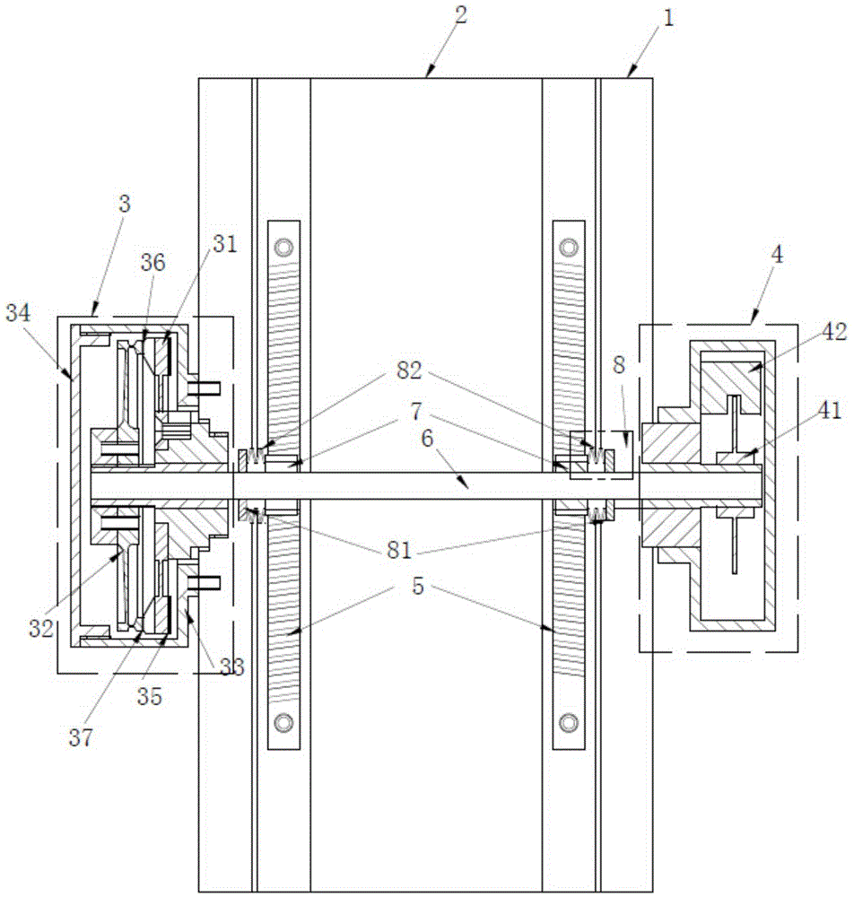
[0010] like figure 1 As shown, a microscope focuser driven by an ultrasonic motor includes a fixed base 1 , a supporting plate 2 , an ultrasonic motor 3 , and an encoder 4 . A ball guide rail is arranged between the supporting plate 2 and the fixed seat 1, and two gear racks 5 are arranged parallelly along the moving direction of the supporting plate on the supporting plate 2, and the gear racks 5 have a horizontal slope. The ultrasonic motor 3 and the encoder 4 are arranged on both sides of the fixed seat 1 respectively, the mandrel 6 of the ultrasonic motor 3 is positioned above the supporting plate 2 and perpendicular to the rack 5, and the encoder 4 is fixed on the side of the ultrasonic motor 3. 6 ends of the mandrel. Two pinion gears 7 are also fixed on the mandrel 6, and the pinion gear 7 also has a horizontal slope, and each pinion gear is meshed with a pinio...


PUM


Abstract

The invention discloses a microscope focusing device based on ultrasonic motor drive. An ultrasonic motor, bevel gears and bevel racks cooperate with one another to electrically control a support plate to move up and down, and the structure is very simple. During usage, the support plate can be controlled to move on any scale under the drive of the ultrasonic motor, so that the clearest focal length can be found out easily. The ultrasonic motor has no inertia during reciprocating, meanwhile, one adjusting mechanism is arranged between one bevel gear and the ultrasonic motor, one adjusting mechanism is arranged between the other bevel gear and an encoder, the bevel gears and the bevel racks can be always meshed closely by the aid of the adjusting mechanisms, and mechanical errors of a traditional structure are avoided when the support plate is controlled to move up and down. The ultrasonic motor, the bevel gears and the bevel racks cooperate with one another, the kinematic accuracy of the support plate is up to plus / minus 2 mu m through experiments, and the focusing accuracy of the focusing device is much higher than that of a traditional focusing structure.

Description

technical field [0001] The invention relates to an electric focuser, in particular to an electric focuser directly driven by an ultrasonic motor. Background technique [0002] In the use of traditional microscopes, when it is necessary to adjust the focal length of the objective lens to the object to be measured, it is mainly realized through the focuser. The recliner is mainly composed of a support plate that moves up and down relative to the fixed seat and a focusing knob. The support plate is driven by turning the adjustment knob, and the optical part of the microscope is installed on the support plate. Traditional microscopes also need to manually adjust the focus and observe its clarity with both eyes. During the process of rotating the focusing knob, it is often necessary to move back and forth clockwise and counterclockwise. It is difficult to control the adjustment amplitude and find the clearest focal length. ; At the same time, there is a mechanical error when adj...

Claims


Application Information

Patent Timeline
Patent Type & Authority Applications(China)
IPC IPC(8): G02B21/00
Inventor 苏勋涛
Owner 苏勋涛
Learn More