System and method for controlling maximum demand on multiple power supply lines

A multi-channel power supply, line control technology, applied in general control systems, control/regulation systems, program control, etc., can solve problems such as inflated maximum demand, loss of production and operation of enterprises, and equipment that cannot be shut down, and achieve the selection process. Fast and accurate, avoid invalid operation, avoid the effect of misoperation

Active Publication Date: 2017-06-16
SHIJIAZHUANG KE ELECTRIC
View PDF6 Cites 0 Cited by
  • Summary
  • Abstract
  • Description
  • Claims
  • Application Information

AI Technical Summary

Problems solved by technology

[0010] The existing problem is: when there is line maintenance or line switching, etc., one line of power supply will be cut off, and the power load will be added to another line or several lines. At this time, the maximum demand will be inflated on the working line. The maximum demand has not changed, but the charging benchmarks on some lines have changed, resulting in unreasonable charging and causing losses to the enterprise
[0012] 1. Some equipment cannot be shut down, and manual selection will inevitably lead to wrong shutdown
[0013] 2. There are few closed devices, and the maximum demand will be inflated after one power supply is cut off.
[0014] 3. There are too many closed devices, which will cause greater losses to the production and operation of the enterprise
[0015] 4. The closed equipment may affect the normal operation of the closed equipment and cause losses

Method used


Image

  • System and method for controlling maximum demand on multiple power supply lines
  • System and method for controlling maximum demand on multiple power supply lines
  • System and method for controlling maximum demand on multiple power supply lines

Examples


Embodiment Construction

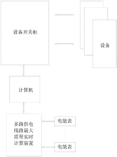
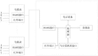
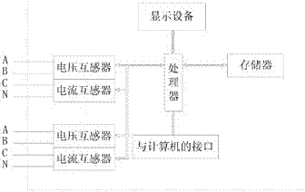
[0053]The system with multiple power supply lines controlling the maximum demand, including computers, equipment switch cabinets, electromagnetic switches for each device in the equipment switch cabinets, computers and electromagnetic switches in the equipment switch cabinets, and the system also includes multiple power supplies connected to computers A real-time calculation device for the maximum demand of a line. The real-time calculation device for the maximum demand of multiple power supply lines includes a processor, an interface with a computer, and an interface for reading power consumption information. The interface for reading power consumption information is connected to at least two power supply lines or power supply lines. Energy meter on power line.

[0054] The power consumption information reading interface can adopt various forms to meet different needs: the RS485 interface or infrared port can be used to connect the existing electric energy meter to read data; ...


PUM


Abstract

The invention, which relates to the power measurement technology, especially to electricity consumption metering and control of the multi-path power supply lines, provides a system and method for controlling a maximum demand of multi-path power supply lines, wherein the system and method are used for controlling power consumption during line repairing and maintenance or line switching. According to the system, a computer is connected with an electromagnetic switch in an equipment switch cabinet; and the system also includes a real-time multi-path power supply line maximum demand calculating device connected with the computer. The real-time multi-path power supply line maximum demand calculating device includes a processor, an interface connected with the computer, and an electricity usage information reading interface; the electricity usage information reading interface is connected with at least two paths of power supply lines or electric energy meters of the power supply lines. The method comprises: priority levels of equipment are set; one piece of equipment that will be turned off is selected according to the priority levels of equipment; total loads of the power supply lines are compared; when a requirement is met, the turning off of the equipment is stopped and the power interruption is prompted to be carried out. According to the system, too much manual intervention is not required and some devices can be selected and turned off automatically, thereby avoiding the unreal increase of the maximum demand.

Description

technical field [0001] The invention relates to power measurement technology, in particular to the power consumption measurement and control of multiple power supply lines. Background technique [0002] Due to the heavy load, large enterprises are powered by two or more lines at the same time, and their basic electricity charges are charged according to the maximum demand. According to the requirements of the power company, for users with two or more incoming lines whose maximum demand charges the basic electricity fee, the maximum demand of each incoming line is calculated separately, and the basic electricity fee is charged accumulatively. [0003] Demand refers to the average value of power over a specified time interval. Maximum demand refers to the maximum value of demand recorded in a specified cycle or billing cycle. [0004] Demand is a measure of power, or more precisely an average power. The specified time interval is the demand period. The demand period in our...

Claims


Application Information

Patent Timeline
Patent Type & Authority Patents(China)
IPC IPC(8): G05B19/042
CPCG05B19/0423
Inventor 李春海陈贺陈洪雨张朋朋袁琳琳刘晓龙侯志卫常生强赵宏杰张向平
Owner SHIJIAZHUANG KE ELECTRIC
Why Eureka
Try Eureka