Control circuit of powder feeder for hypersonic flame spraying

A supersonic flame, control circuit technology, applied in general control systems, program control, electrical program control, etc., can solve the problems of low processing efficiency, poor controllability, and the spraying process cannot be carried out normally, so as to reduce costs and improve delivery. The effect of powder efficiency

Active Publication Date: 2015-09-30
WUHU DINGHENG MATERIAL TECH
View PDF3 Cites 0 Cited by
  • Summary
  • Abstract
  • Description
  • Claims
  • Application Information

AI Technical Summary

Problems solved by technology

However, the traditional powder feeder mostly adopts a single-channel powder feeding method, which has poor controllability, affects the final spraying effect, and has low processing efficiency. Once the equipment fails, the spraying process will not be able to proceed normally.

Method used


Image

  • Control circuit of powder feeder for hypersonic flame spraying

Examples


Embodiment Construction

[0014] In order to make the technical means, creative features, goals and effects achieved by the present invention easy to understand, the present invention will be further elaborated below.

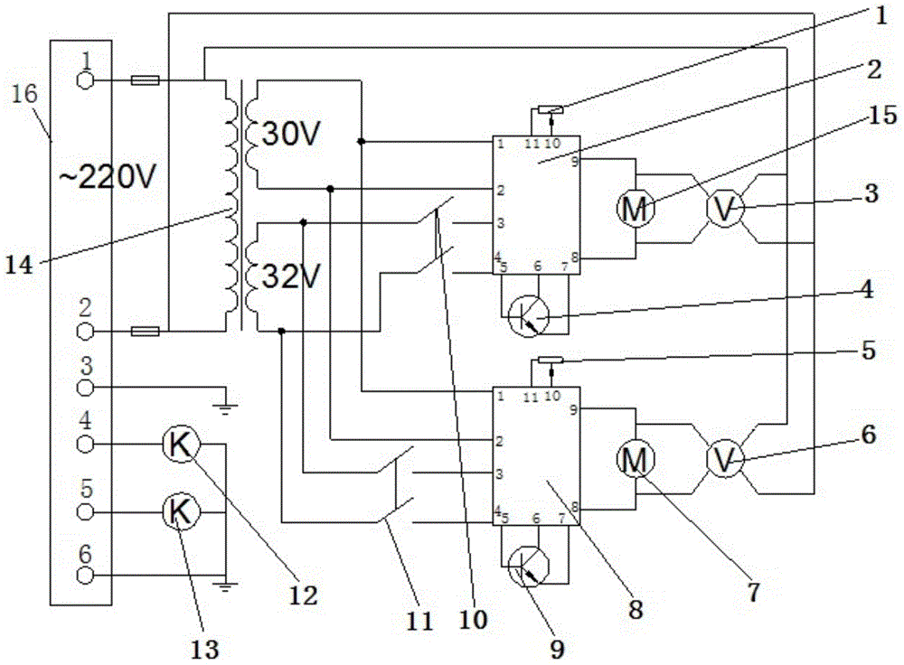
[0015] Such as figure 1 As shown, a control circuit of a powder feeder for supersonic flame spraying, including potentiometer one 1, speed control board one 2, voltmeter one 3, power tube one 4, potentiometer two 5, voltmeter two 6, motor Two 7, speed control board two 8, power tube two 9, switch one 10, switch two 11, solenoid valve one 12, solenoid valve two 13, transformer 14, motor one 15 and plug-in strip 16, and the transformer 14 includes incoming lines side, 30V output terminal and 32V output terminal, the incoming line side of the transformer 14 is connected to 220V alternating current and then connected to pin 1 and pin 2 of the socket 16, and pin 1 and pin 2 of the speed control board 1 are respectively connected to On the 30V output terminal of the transformer 14, the 32V o...


PUM


Abstract

The invention relates to a control circuit of powder feeder for hypersonic flame spraying, comprising a first potentiometer, a first speed control panel, a first voltmeter, a first power tube, a second potentiometer, a second voltmeter, a second motor, a second speed control panel, a second power tube, a first switch, a second switch, a first electromagnetic valve, a second electromagnetic valve, a transformer, a first motor and a power strip. The first motor and the second motor allows two feeding branches to be controlled; compared with the traditional single-channel feeding way, the feeding way using the two motors has the advantages that feeding efficiency is improved, the single device is used for two hypersonic flame spraying devices, the production cost is lowered, a replacement function is good, if one feeding branch has a control fault, the other feeding branch can be controlled instead, and smooth spraying is guaranteed.

Description

technical field [0001] The invention relates to the technical field of supersonic flame spraying, in particular to a control circuit of a powder feeder for supersonic flame spraying. Background technique [0002] Except for a few precious metals, metal materials will undergo chemical and electrochemical reactions with the surrounding medium and suffer from corrosion. In addition, the wear and tear caused by various mechanical actions on the metal surface is also extremely serious. A large number of metal components fail due to corrosion and wear, resulting in great waste and loss. With the continuous development of science and technology, remanufacturing technology has also been applied. According to the documents jointly issued by 11 departments including the Development and Reform Commission, the Ministry of Science and Technology, the Ministry of Industry and Information Technology, the Ministry of Public Security, the Ministry of Finance, the Ministry of Environmental ...

Claims


Application Information

Patent Timeline
Patent Type & Authority Applications(China)
IPC IPC(8): G05B19/05
CPCG05B19/05G05B19/054
Inventor 程敬卿
Owner WUHU DINGHENG MATERIAL TECH
Why Eureka
Try Eureka