Variable-frequency air conditioner, power circuit of outdoor unit of variable-frequency air conditioner and PFC (power factor correction) control method

An inverter air conditioner and power circuit technology, which is applied in the direction of high-efficiency power electronic conversion, electrical components, output power conversion devices, etc. life and other issues, to achieve the effect of extending the service life, reducing production costs, and reducing the total capacity

Inactive Publication Date: 2015-09-30
GD MIDEA AIR-CONDITIONING EQUIP CO LTD +1
View PDF5 Cites 11 Cited by
  • Summary
  • Abstract
  • Description
  • Claims
  • Application Information

AI Technical Summary

Problems solved by technology

[0003] exist figure 1 In the related technology, during the actual operation of the inverter air conditioner, the bus voltage fluctuation caused by the load will generate a ripple current flowing through the electrolytic capacitors E11' and E21', and each electrolytic capacitor will bear 1/2 of the total ripple Current, the ripple current borne by each electrolytic capacitor and the equivalent series resistance of the electrolytic capacitor itself will generate active power, which will eventually be converted into heat ener

Method used


Image

  • Variable-frequency air conditioner, power circuit of outdoor unit of variable-frequency air conditioner and PFC (power factor correction) control method
  • Variable-frequency air conditioner, power circuit of outdoor unit of variable-frequency air conditioner and PFC (power factor correction) control method
  • Variable-frequency air conditioner, power circuit of outdoor unit of variable-frequency air conditioner and PFC (power factor correction) control method

Examples


Embodiment Construction

[0026] Embodiments of the present invention are described in detail below, examples of which are shown in the drawings, wherein the same or similar reference numerals designate the same or similar elements or elements having the same or similar functions throughout. The embodiments described below by referring to the figures are exemplary and are intended to explain the present invention and should not be construed as limiting the present invention.

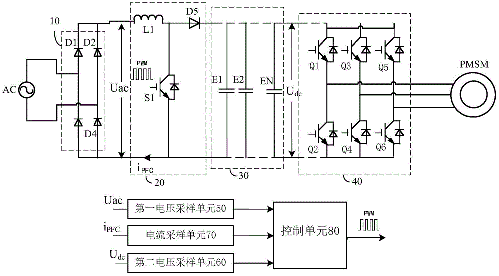
[0027] The following describes the power circuit of the outdoor unit in the inverter air conditioner, the inverter air conditioner with the power circuit, and the PFC control method for the power circuit of the outdoor unit in the inverter air conditioner proposed by the embodiments of the present invention with reference to the accompanying drawings. According to an example of the present invention, the power supply circuit of the outdoor unit may be a high-voltage main power supply filter circuit.

[0028] figure 2 It is a sc...


PUM


Abstract

The invention discloses a variable-frequency air conditioner, a power circuit of an outdoor unit of the variable-frequency air conditioner and a PFC (power factor correction) control method. The power circuit comprises a rectifying circuit, a PFC circuit, an electrolytic capacitor group, a three-phase inverting circuit, a first voltage sampling unit, a second voltage sampling unit, a current sampling unit and a control unit, wherein the electrolytic capacitor group comprises N electrolytic capacitors connected in parallel and is connected between a positive terminal of a direct-current bus and a negative terminal of the direct-current bus, and N is an integer larger than 2; the first voltage sampling unit is used for sampling voltage Uac input to the PFC circuit; the second voltage sampling unit is used for sampling voltage Udc of the direct-current bus; the current sampling unit is used for sampling current iPFC of the PFC circuit during working; the control unit is used for generating control signals according to the voltage Uac, the voltage Udc and the current iPFC to control the PFC circuit, and reducing ripple voltage borne by the electrolytic capacitor group through closed-loop control on voltage of the direct-current bus. Therefore, ripple current is shared by the N electrolytic capacitors, the ripple current borne by each electrolytic capacitor is reduced, the heat generating amount of each electrolytic capacitor is reduced, the reliability of each electrolytic capacitor is improved, and the service life of each electrolytic capacitor is prolonged.

Description

technical field [0001] The invention relates to the technical field of air conditioning, in particular to a power circuit of an outdoor unit in an inverter air conditioner, an inverter air conditioner, and a PFC control method for the power circuit of an outdoor unit in the inverter air conditioner. Background technique [0002] The power supply circuit of the outdoor unit of the related inverter air conditioner is generally equipped with electrolytic capacitors, and the heat generated by the electrolytic capacitors during use will affect the performance of the electrolytic capacitors, thereby reducing the reliability of the electrolytic capacitors and shortening the service life of the electrolytic capacitors, resulting in electrolytic capacitors. An important reason for the heating of the capacitor during use is the ripple current flowing through the electrolytic capacitor itself. The larger the ripple current, the higher the temperature rise of the corresponding electrolyt...

Claims


Application Information

Patent Timeline
IPC IPC(8): H02M5/458H02M1/42
CPCY02B70/10
Inventor 管晓文
Owner GD MIDEA AIR-CONDITIONING EQUIP CO LTD
Why Eureka
Try Eureka