Eureka AIR delivers breakthrough ideas for toughest innovation challenges, trusted by R&D personnel around the world.

Rotary drives for construction machinery

A technology of slewing drive and construction machinery, applied in the direction of earth mover/shovel, construction, etc., can solve the problems of increased friction loss, energy loss, and large friction loss effect, so as to increase the size and reduce the energy loss. , the effect of increasing the deceleration ratio

Active Publication Date: 2017-03-08
DOOSAN INFRACORE CO LTD
View PDF6 Cites 0 Cited by
  • Summary
  • Abstract
  • Description
  • Claims
  • Application Information

AI Technical Summary

Problems solved by technology

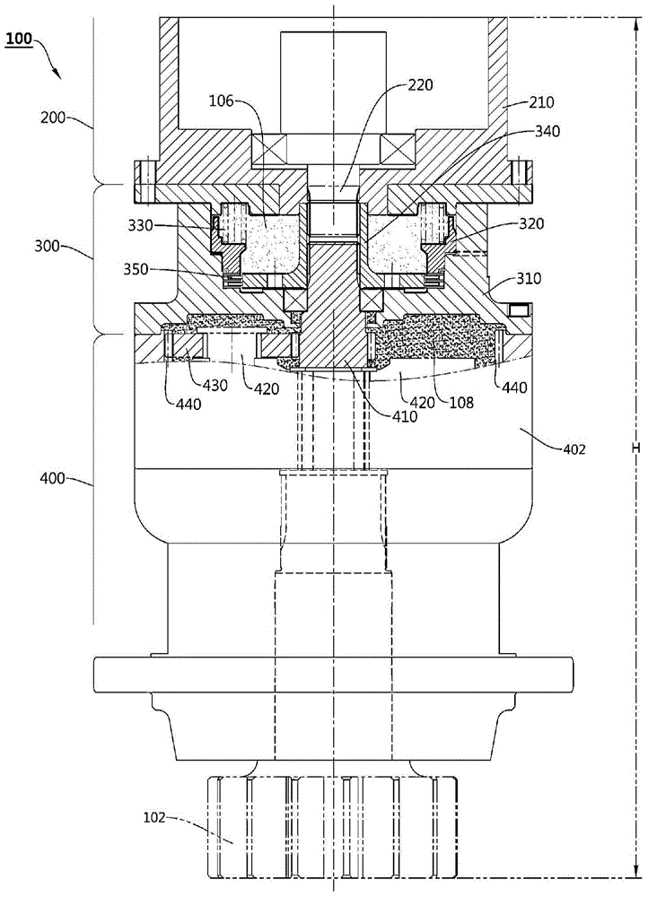
[0023] Thus, with regard to the conventionally known rotary drive device (100), if a certain specific gear is provided smaller simply to increase the deceleration ratio of the second-speed transmission, there is a problem of reduced durability. If a specific gear is provided, the rotary drive device (100) is too large in size and takes up a lot of space, so there is a practical problem that it is difficult to add it to construction machinery
[0024] On the other hand, although there is a proposal that the reduction gear unit (sun gear, planetary carrier, planetary gear, ring gear) is constituted by three layers in the reduction unit (400), in this case, the rotary drive device (100) The overall height (refer to H) will increase, and there is a practical problem that it is difficult to install on construction machinery due to the space occupied
[0025] In addition, in the proposal that the reduction gear unit (sun gear, planetary carrier, planetary gear, and ring gear) is composed of three layers in the reduction unit (400), when high-speed rotation is realized, the brake unit (300) is filled with The friction loss caused by the working oil (106) has a large effect, and energy loss will occur
In particular, inside the reduction unit (400), the three-layer reduction gear structure rubs against the gear oil (108), so when the reduction structure rotates at high speed, there is friction loss due to the highly viscous gear oil (108). greatly increased worry

Method used


Image

  • Rotary drives for construction machinery
  • Rotary drives for construction machinery
  • Rotary drives for construction machinery

Examples


Embodiment Construction

[0070] If referring to the following and attached Figure 1 With the detailed description of the embodiment, the advantages, features and methods for achieving the present invention will be clarified.

[0071] Embodiments of the present invention will be described in detail below with reference to the accompanying drawings. The embodiments described below are exemplarily shown to help the understanding of the present invention, and it should be understood that the present invention can be variously modified and implemented differently from the embodiments described here. However, when describing the present invention, when it is judged that the specific description of related known functions or components may unnecessarily obscure the gist of the present invention, the detailed description and specific illustrations will be omitted. In addition, in order to facilitate the understanding of the invention, the drawings are not shown on an actual scale, and the sizes of some comp...


PUM


Abstract

The present invention relates to a rotary driving device of a construction machine, and more specifically, to a rotary driving device of a construction machine for rotating an upper body in a lower body. The slewing drive device of construction machinery of the present invention provides the external size of the slewing drive device with the same or equivalent size as the conventional slewing drive device, and at the same time increases the deceleration ratio to improve power output and torque. The rotary drive device of the construction machine according to the present invention can reduce the energy loss caused by the working oil when the rotary drive device is driven at a high speed.

Description

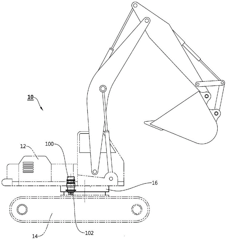
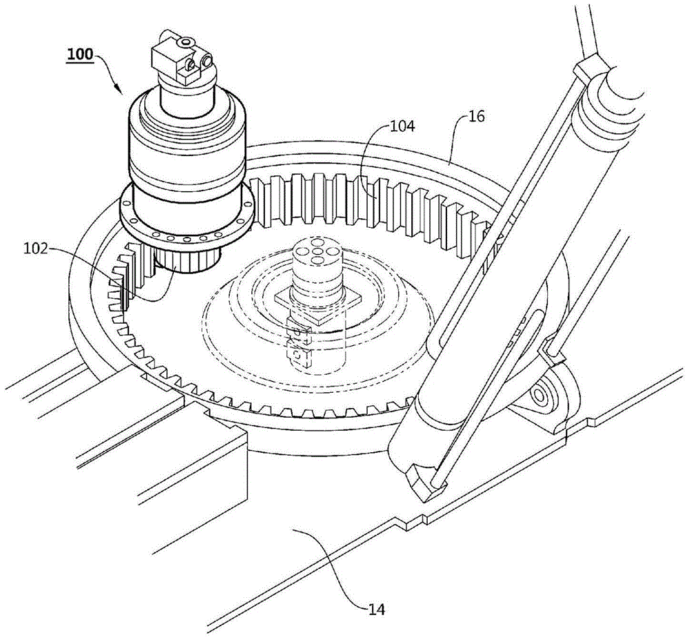
technical field [0001] The present invention relates to a rotary driving device of a construction machine, and more specifically, to a rotary driving device of a construction machine for rotating an upper body in a lower body. Background technique [0002] Generally speaking, construction machinery (10) such as figure 1 The assembly shown is such that the upper body (12) and the lower body (14) can be turned around by means of the connecting unit (16). A turning drive device (100) is provided inside the connection unit (16). [0003] In more detail, the rotary driving device (100) is fixed on the upper body (12), such as figure 2 As shown, a rotary drive gear (102) is provided on the lower side of the rotary drive device (100), and a rotary driven gear (104) is formed on the connection unit (16) on the lower body (14) side. The rotary drive gear (102) is internally engaged with the rotary driven gear (104) to realize gear transmission. [0004] with reference to the att...

Claims


Application Information

Patent Timeline
Patent Type & Authority Patents(China)
IPC IPC(8): E02F9/12
CPCE02F9/123E02F9/12
Inventor 金敬根
Owner DOOSAN INFRACORE CO LTD
Why Eureka
Eureka Blog
Learn More