Eureka AIR delivers breakthrough ideas for toughest innovation challenges, trusted by R&D personnel around the world.

Motor driving device for motor-bicycle

A technology driven by electric bicycles and motors, applied in the direction of electric power devices, bicycles, power devices, etc., can solve the problems of weight increase, large noise of meshing parts, increase of outer diameter, etc., and achieve diameter and weight reduction, high deceleration ratio, noise Reduced effect

Inactive Publication Date: 2005-08-03
YAMAHA MOTOR CO LTD
View PDF0 Cites 1 Cited by
  • Summary
  • Abstract
  • Description
  • Claims
  • Application Information

AI Technical Summary

Problems solved by technology

[0005] However, there is a problem in the conventional electric bicycle motor driving device that when the motor and the planetary gear mechanism are arranged around a single axle, the outer diameter of the entire motor driving device increases, and its weight also increases.
[0007] Another problem is that the meshing parts make a lot of noise because planetary transmissions have a lot of meshing parts when two planetary transmissions are placed side by side to provide two-stage gear reduction

Method used


Image

  • Motor driving device for motor-bicycle
  • Motor driving device for motor-bicycle
  • Motor driving device for motor-bicycle

Examples


no. 1 example

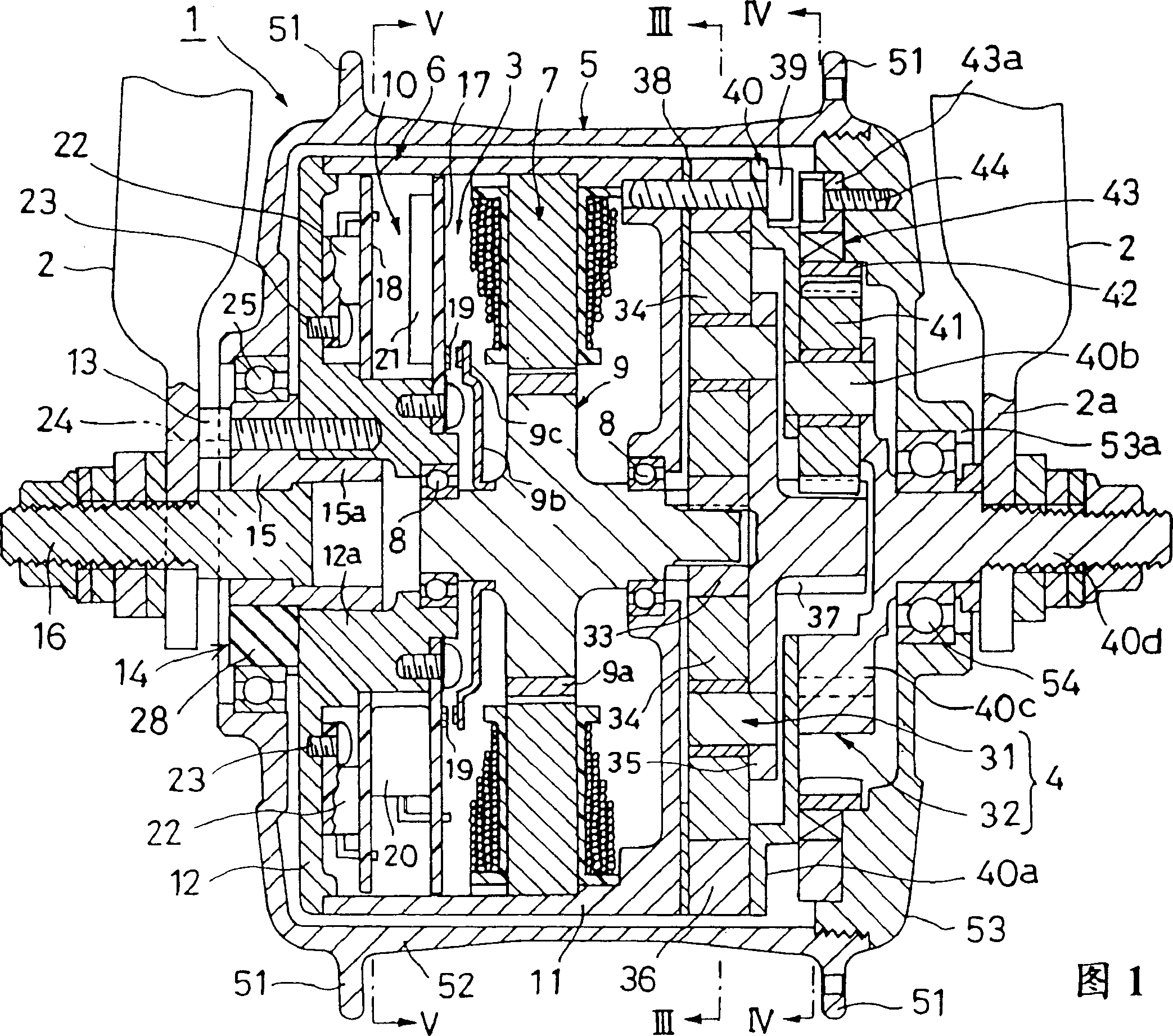
[0033] An embodiment of the electric bicycle motor drive device of the present invention will be described in detail below with reference to accompanying drawings 1 to 5.

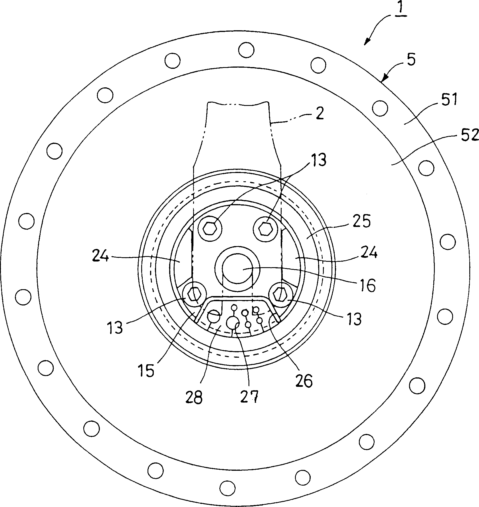
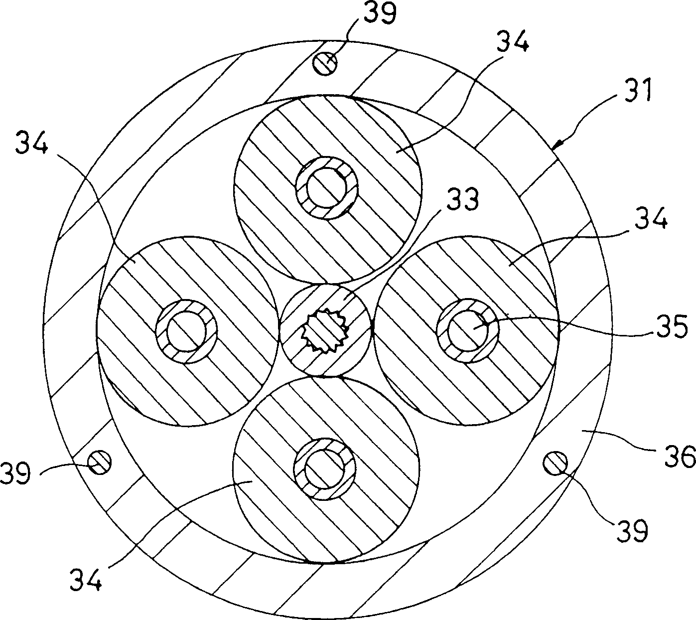
[0034] Fig. 1 is a sectional view of the motor drive device of the electric bicycle of the present invention. figure 2 An end-on-side view of the motor of the motor drive is shown. image 3 It is a sectional view taken along line III-III of the planetary roller transmission shown in FIG. 1 . Figure 4 It is a sectional view taken along line IV-IV of the planetary gear transmission shown in FIG. 1 . Figure 5 is a view of a substrate on which capacitors are mounted, seen along the section line V-V in FIG. 1 .

[0035] In the drawings, the motor driving device of the electric bicycle of this embodiment is represented by reference numeral 1 . The motor drive 1 is located in the axial part of the front wheel and is connected to the front fork indicated by reference numeral 2 in FIG. 1 . In the structure of ...

no. 2 example

[0066] The motor driving device of the electric bicycle of the present invention may adopt a structure arranged in the axial portion of the rear wheel. Such an embodiment will be described in detail below with reference to FIG. 6 .

[0067] Figure 6 is a cross-sectional view of such an embodiment. In FIG. 6, the same or equivalent components as those described with reference to FIGS. 1 to 4 have the same or corresponding reference numerals, and thus will not be described again.

[0068] The structure of the motor driving device 61 shown in FIG. 6 is partially modified on the basis of the front wheel motor driving device in the first embodiment. Two modifications made will be described below.

[0069] The first point of modification concerns a part of the device where the device is attached to the vehicle body frame 62 . That is, because the distance between the two end frames 63 for supporting the rear wheel of the bicycle is greater than the distance between the end frames...


PUM


Abstract

To reduce size and weight of a motor drive unit with an electric motor disposed on the hub side. An electric motor 3 is disposed on one end, in the vehicle width direction, of a hub 5. A planetary transmission 4 for transmitting the rotation of the rotor 9 of the motor 3 from a sun member to the hub 5 through planetary members and an outer circumferential member is disposed on the other side. A wheel shaft is constituted with an assembled set of a motor housing 6 and a carrier 40 of the planetary transmission 4.

Description

technical field [0001] The invention relates to a motor driving device of an electric bicycle, wherein a motor is arranged in a wheel hub of a wheel. Background technique [0002] A Japanese Patent Application Laid-Open Publication No. Hei-9-39872 discloses a conventional electric bicycle motor drive device in which the motor is arranged near the wheel shaft. In the structure of the motor drive device described in this gazette, a motor and a planetary gear transmission are arranged side by side in the width direction of the vehicle and coaxially supported on the wheel shaft fixed to the vehicle body frame so that the output shaft of the motor The rotational speed is reduced by the planetary gear transmission and transmitted to the hub. The shape of the hub is such that it covers the planetary transmission and is supported to rotate on the axle. [0003] The motor has a housing fixed to the frame of the vehicle body and an output shaft protruding toward the planetary gear t...

Claims


Application Information

Patent Timeline
IPC IPC(8): B62M6/65B62M7/12B62M11/16
CPCB62M11/16B62M7/12B62M6/65
Inventor 中之薗晴彦
Owner YAMAHA MOTOR CO LTD
Why Eureka
Eureka Blog
Learn More