
Converter and method for operating same

A converter, power flow technology, applied in the field of converters, can solve the problems of converter construction space requirements, production cost and weight adverse effects, high intermediate circuit voltage, damage, etc.

Inactive Publication Date: 2015-09-30
SIEMENS AG
View PDF5 Cites 0 Cited by
  • Summary
  • Abstract
  • Description
  • Claims
  • Application Information

AI Technical Summary

Problems solved by technology

If the intermediate capacitor is not dimensioned sufficiently large, this can lead to an impermissibly high intermediate circuit voltage and thus to an overload or even damage to the converter.
However, the larger designed intermediate circuit capacitors have a negative impact on the constructional space requirements, production costs and weight of the converter

Method used


Image

  • Converter and method for operating same
  • Converter and method for operating same
  • Converter and method for operating same

Examples


Embodiment Construction

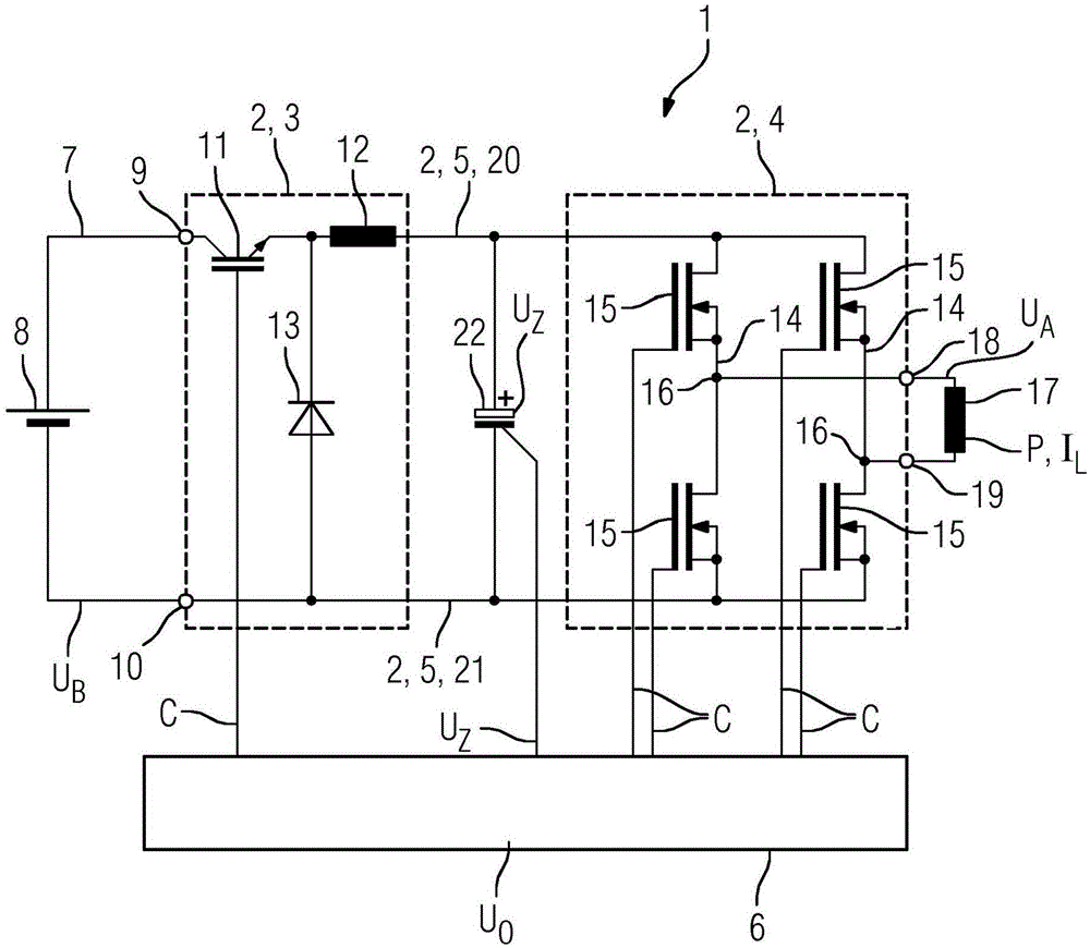
[0029] figure 1 A converter 1 is shown having a single (converter) module 2 which is formed by a primary switching circuit 3 , a secondary switching circuit 4 and an intermediate circuit 5 . The converter 1 also includes a control device 6 .

[0030] The primary switching circuit 3 is designed to be connected on the input side to a (voltage) network 7 , which in the illustrated embodiment is a DC voltage network supplied by a battery 8 and via which the primary switching circuit 3 is connected via the input terminal 9 and 10 deliver the battery voltage U B .

[0031] Correspondingly, the primary switching circuit 3 is designed as a DC regulator. in accordance with figure 1 In an embodiment, it is specifically a single-quadrant regulator in the form of a simple buck regulator. The primary switching circuit 3 is essentially formed here by a semiconductor switch 11 , designed here as an IGBT, which is connected to the positive pole of the battery 8 at an input terminal 9 , a...


PUM


Abstract

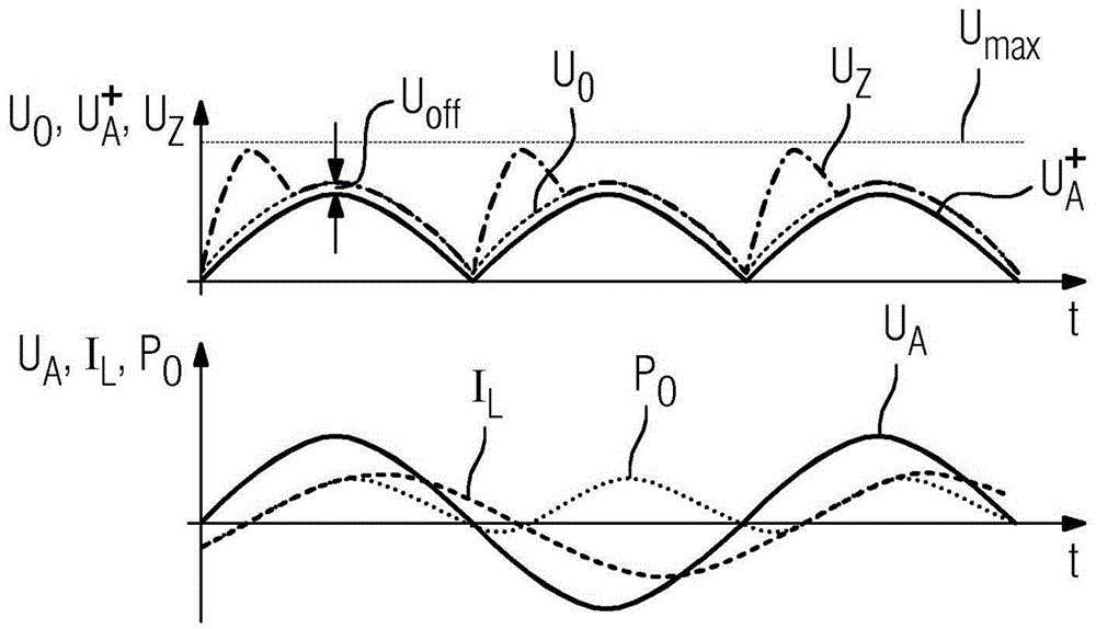
The method involves setting an intermediate circuit voltage (Uz) that drops along intermediate circuit capacitance (22) i.e. capacitor, to determined desired voltage reference value (Uo) by controlling a primary switching circuit (3) i.e. quadrant actuator, of a converter module (2) of a converter (1). The voltage reference value is variably determined depending on a direction of a power flow in a secondary switching circuit (4) of the converter module, where the primary switching circuit is connected to a power network (7) and the secondary switching circuit is connected to a load (17). An independent claim is also included for a converter.

Description

technical field [0001] The invention relates to a converter having at least one converter module, but preferably a plurality of converter modules. Furthermore, the invention relates to a method for operating such a converter. Background technique [0002] Converters are used in electric drive technology to supply electric loads, in particular electric motors, with electric power from a (voltage) network. An exemplary field of application for the converter is the supply of drive motors or drive motors of electric vehicles. In this case, the voltage network is the battery circuit of the traction battery of the vehicle—carrying direct current. In stationary applications, on the contrary, the primary side of the converter is usually connected to a single-phase or multi-phase AC voltage network. [0003] A converter usually comprises a primary switching circuit for connection to the network and a secondary coil for connection to the load. The primary coil and the secondary co...

Claims


Application Information

Patent Timeline
Patent Type & Authority Applications(China)
IPC IPC(8): H02J7/34B60L7/10
CPCH02J7/345B60L2210/30B60L2210/40B60L15/007B60L7/14B60L2240/527B60L2240/547B60L2240/529H02M7/493Y02T10/64Y02T10/72H02M7/5387H02P3/14
Inventor 胡贝特·席尔林
Owner SIEMENS AG
Learn More