
Traction trolley driven transport hopper

A technology for pulling trolleys and hoppers, applied to supply devices, manufacturing tools, etc., can solve the problems of difficult construction, low production efficiency, and high equipment costs, and achieve the goal of reducing equipment costs and construction difficulties, improving production efficiency, and improving transportation efficiency. Effect

Inactive Publication Date: 2015-10-07
张波
View PDF9 Cites 12 Cited by
  • Summary
  • Abstract
  • Description
  • Claims
  • Application Information

AI Technical Summary

Problems solved by technology

[0002] At present, in the industrial production of prefabricated components in the construction field, a transport hopper with a power source is generally used to transport concrete between the concrete mixing station and the concrete placing machine. The transport hopper travels reciprocally along the track, but because the existing transport hopper cannot Turning, but also does not have climbing performance, so in order to ensure that the track between the concrete mixing plant and the filling position of the concrete distributor is a horizontal straight track during equipment construction, it is usually necessary to raise the concrete mixing plant, resulting in relatively high equipment costs , the construction is difficult, which is not conducive to making full use of the internal space of the factory area, the transportation efficiency of the reciprocating transport hopper is also very limited, and the production efficiency is relatively low

Method used


Image

  • Traction trolley driven transport hopper
  • Traction trolley driven transport hopper
  • Traction trolley driven transport hopper

Examples


Embodiment Construction

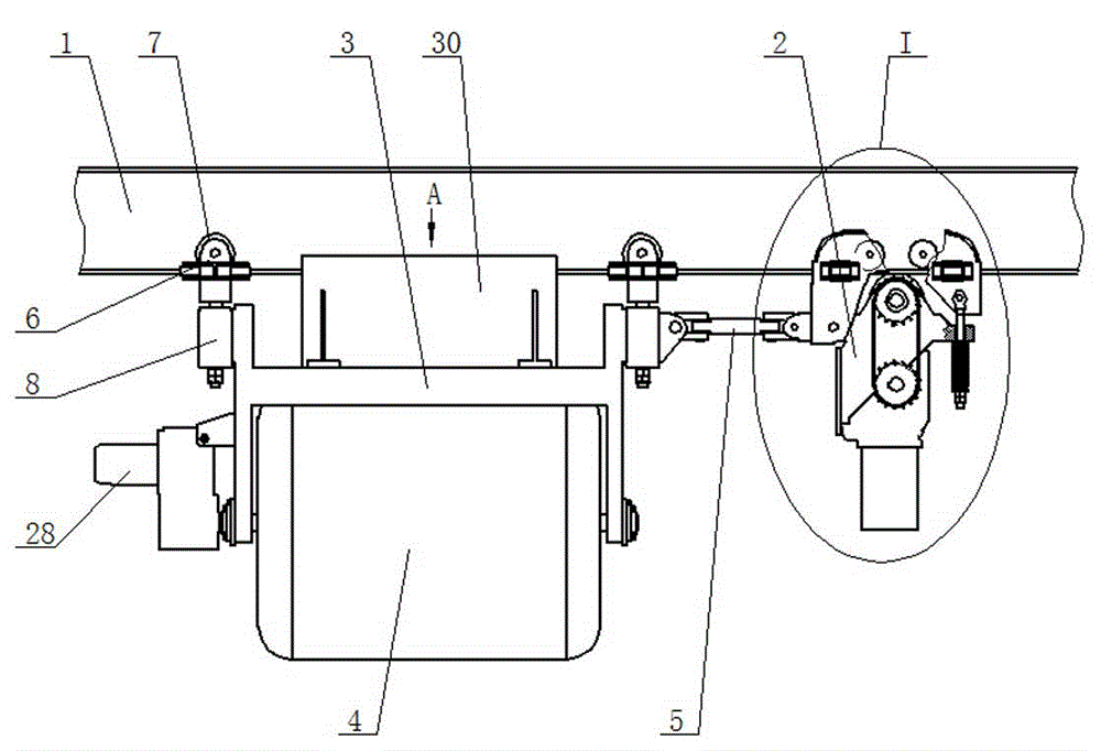
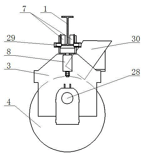
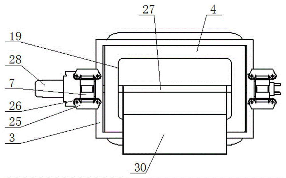
[0014] A transport hopper driven by a traction trolley according to the present invention comprises a track 1, a traction trolley 2 is installed on the track 1, a hopper suspension wheel set 6 is installed on the track 1, and the driven suspension wheel 7 in the hopper suspension wheel set 6 and the track 1 Cooperate, the hopper hanging wheel group 6 is connected with the hopper frame 3 through the wheel group longitudinal rotation assembly 8, the hopper hanging wheel group 6 can rotate relative to the vertical direction of the hopper frame 3, the hopper frame 3 is installed with the hopper 4, and the top of the hopper 4 is provided with a feed inlet 19. A discharge device is installed on the hopper 4, and a connecting rod 5 is set between the traction trolley 2 and the hopper frame 3. One end of the connecting rod 5 is connected to the traction trolley 2 through a universal joint, and the other end of the connecting rod 5 is connected to the hopper frame through a universal joi...


PUM


Abstract

A traction trolley driven transport hopper comprises tracks. A traction trolley is mounted on one track. Hopper hanging wheel sets are mounted on the tracks. Driven hanging wheels in the hopper hanging wheel sets are matched with the tracks. Hopper hanging wheels are connected with a hopper frame through longitudinal wheel set rotating assemblies. A hopper is mounted on the hopper frame. The top of the hopper is provided with a feed port. The hopper is provided with an unloading device. A connecting rod is arranged between the traction trolley and the hopper frame. One end of the connecting rod is connected with the traction trolley through a cardan joint. The other end of the connecting rod is connected with the hopper frame through a cardan joint. The hopper frame can be driven by the traction trolley to move along the tracks. The traction trolley driven transport hopper can run along the bent and inclined annular tracks and has good climbing performance; a concrete batching plant is built at a selected appropriate place and does not need to be elevated, and the equipment cost and construction difficulty can be reduced; a plurality of transport hoppers can be mounted on the annular tracks for cyclically conveying, and therefore the transportation efficiency of the transport hopper can be substantially improved, and the production efficiency can be improved.

Description

technical field [0001] The invention relates to a concrete transfer device, in particular to a transport hopper driven by a traction trolley. Background technique [0002] At present, in the industrial production of prefabricated components in the construction field, a transport hopper with a power source is generally used to transport concrete between the concrete mixing station and the concrete placing machine. The transport hopper travels reciprocally along the track, but because the existing transport hopper cannot Turning, but also does not have climbing performance, so in order to ensure that the track between the concrete mixing plant and the filling position of the concrete distributor is a horizontal straight track during equipment construction, it is usually necessary to raise the concrete mixing plant, resulting in relatively high equipment costs , The construction is difficult, which is not conducive to making full use of the internal space of the factory area. T...

Claims


Application Information

Patent Timeline
Patent Type & Authority Applications(China)
IPC IPC(8): B28B13/02
CPCB28B13/023
Inventor 邱正勋张波
Owner 张波
Learn More