System and method for controlling urban rail transit platform gap automatic compensation mechanism

A technology for urban rail transit and automatic compensation, applied in the field of rail transit, can solve the problems of scratching the car body and cannot fundamentally solve the gap, etc., and achieves the effect of convenient use and good application prospects.

Active Publication Date: 2015-10-07
NANJING KANGNI ELECTRONICS TECH
7 Cites 8 Cited by

AI-Extracted Technical Summary

Problems solved by technology

[0005] The purpose of the present invention is to overcome the existing fixed platform compensator to compensate the gap between the platform and the car body of the urban rail train, which often rubs against the car body during the operation of the train, and can only fill a small part of the gap. Gap, can not fundamentally solve the problem of gap
Compared with the prior art, the urban rail transit platform gap autom...

Method used

[0035] The door machine controller 6 is also connected with a manual unlock switch 9, an isolating switch 10, and the isolating switch 10 is use...

Abstract

The invention discloses a system and method for controlling an urban rail transit platform gap automatic compensation mechanism. The system comprises a turnover pedal, a turnover mechanism, a turnover motor, a turnover motor controller, an expansion-in-place detecting switch, a door controller and an upper computer, wherein the turnover pedal is mounted on the external side of a safety door threshold through the turnover mechanism; the turnover motor is positioned on one side of the turnover mechanism to control the turnover of the turnover mechanism so as to expand or retract the turnover pedal; the expansion-in-place detecting switch is positioned on the other side of the turnover mechanism; the turnover motor is connected with the turnover motor controller; the expansion-in-place detecting switch is connected with the door controller; and the turnover motor controller and the door controller are connected with the upper computer, respectively. According to the invention, as a platform gap compensator and a safety door are linked with each other, passengers are prevented from missing steps or dropping small articles to rails and the problem that the vehicle body may be scratched by a fixed platform gap compensator is solved; and the system and method for controlling the urban rail transit platform gap automatic compensation mechanism, disclosed by the invention, has the advantages of safety, reliability, convenience in use and good application prospect.

Application Domain

Railway componentsRailway station

Technology Topic

Image

  • System and method for controlling urban rail transit platform gap automatic compensation mechanism
  • System and method for controlling urban rail transit platform gap automatic compensation mechanism
  • System and method for controlling urban rail transit platform gap automatic compensation mechanism

Examples

  • Experimental program(1)

Example Embodiment

[0031] The present invention will be further explained below in conjunction with the accompanying drawings of the specification. The following embodiments are only used to illustrate the technical solutions of the present invention more clearly, and cannot be used to limit the protection scope of the present invention.
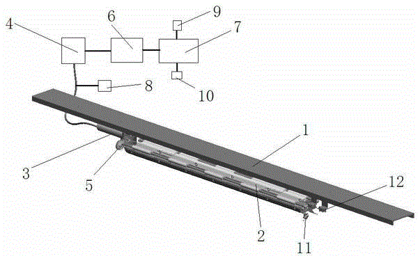
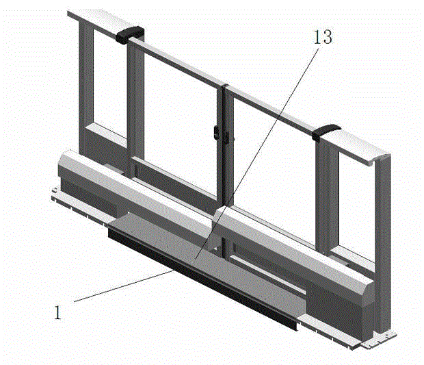
[0032] The urban rail transit platform gap automatic compensation mechanism control system of the present invention enables the platform gap compensator to be linked with the safety door, which not only prevents passengers from stepping on or small items falling to the track, but also solves the problem of fixed platform gap compensator The problem of scratching the car body is safe, reliable and easy to use, such as figure 1 As shown, it includes the flip pedal 1, the flip mechanism 2, the flip motor 3, the flip motor controller 4, the telescopic in-position detection switch 5, the door machine controller 6 and the upper computer 7, such as figure 2 As shown, the flipping pedal 1 is installed on the outside of the safety door sill 13 through the flipping mechanism 2. The flipping motor 3 is located on one side of the flipping mechanism 2, and the flipping mechanism 2 is controlled to flip to realize the unfolding or retracting of the flipping pedal 1. The in-position detection switch 5 is located on the other side of the turning mechanism 2, and is used to detect whether the turning pedal 1 is in place or not. The turning plate motor 3 is connected to the turning plate motor controller 4, and the telescopic position detection switch 5 It is connected with the door machine controller 6, and the flap motor controller 4 and the door machine controller 6 are respectively connected with the upper computer 7.
[0033] The flipping pedal 1, flipping mechanism 2, flipping motor 3, flipping motor controller 4, telescopic in-position detection switch 5, and door operator controller 6 are multiple groups, and the number is the same as the number of safety doors on one side of the rail transit vehicle. The platform clearance of each safety door.
[0034] The present invention also includes an emergency operation switch 8 which is connected with the flipping motor 3, and in an emergency state, the operation of the flipping motor 3 is manually controlled.
[0035] The door operator controller 6 is also connected with a manual unlocking switch 9 and an isolating switch 10, and the isolating switch 10 is used to isolate the high-voltage and low-voltage sides of the platform gap compensation system to improve the safety and reliability of the system.
[0036] The turning mechanism 2 is a multi-link hinge mechanism. The turning pedal 1 is movably installed at the bottom of the outer side of the safety door sill 13 through a multi-link hinge mechanism. The turning pedal 1 is flush with the safety door sill 13 after being unfolded. The dead center of the hinge mechanism ensures that the movable flipping pedal 1 will not fall due to power failure or external force. The flipping pedal 1 is also connected with a bypass switch 11 and a limit switch 12.
[0037] Such as image 3 As shown, the door operator controller 6 is provided with five input ports and two output ports. The five input ports are the signal of turning pedal in position, the signal of turning pedal received, the signal of turning pedal bypass, the signal of turning pedal manual unlocking and Flip pedal fault feedback signal, flip pedal extension signal, flip pedal received position signal is directly connected to telescopic in-position detection switch 5, used to detect the current flipping state; flip pedal bypass signal and a pair of normally open bypass switch 11 The contacts are connected to monitor whether the current pedal is in an obstacle state. The manual unlocking signal of the flap is connected with the manual unlocking switch 9 to detect whether the flap is in the manual unlocking state; the pedal fault feedback signal is controlled by the intermediate relay and the flap motor The two output ports of the door machine controller 6 are the unfolding or retracting signal of the flipping pedal, the flipping pedal enable signal, and the flipping pedal enable signal. It is used to control and turn the pedal into working state to improve safety performance.
[0038] The two input ports of the flipping motor controller 4 are the flipping pedal enable signal and the flipping pedal expansion or retracting signal, which are connected to the door machine controller 6 to receive, and one output signal is the electric flipping fault signal, which passes through the intermediate relay. Connect with door machine controller 6.
[0039] The control method based on the above-mentioned urban rail transit platform gap automatic compensation mechanism control system includes the following steps:
[0040] Step (1): When the rail transit vehicle arrives at the station, the door operator controller 6 of each safety door receives the door opening signal, and the door operator controller 6 outputs the unfolding and turning pedal signal to the flap motor controller 4;
[0041] Step (2), the flipping motor controller 4 controls the flipping motor 3 to rotate, and the flipping motor 3 drives the flipping mechanism 2 to flip to realize the flipping pedal 1 is extended upward;
[0042] Step (3), after the delay, the door machine controller 6 controls the opening of the safety door, and at the same time detects the extension in position signal sent by the telescopic in-position detection switch 5, the door machine controller 6 outputs the unfolding and flipping pedal signal. After the delay, if not received If the position signal is received, it is judged as a fault, and an audible and visual alarm is output; if the extension signal is received, the rollover pedal 1 is normally deployed;
[0043] Step (4), before the rail transit vehicle leaves the station, the door operator controller 6 of the safety door receives the door closing signal, closes and locks the safety door, and outputs the retractable pedal signal to the flap motor controller 4;
[0044] Step (5), the flipping motor controller 4 controls the flipping motor 3 to rotate, and the flipping motor 3 drives the flipping mechanism 2 to flip to realize the flipping pedal 1 is retracted downward;
[0045] Step (6): After the delay, the door machine controller 6 detects the received bit signal sent by the telescopic in-position detection switch 5. If the received bit signal is not received, it is judged as a failure and an audible and visual alarm is output; if the received bit signal is received , The folding pedal 1 is normal;
[0046] Step (7), the limit switch 12 is triggered after the flip pedal 1 is retracted, and the contact of the limit switch 12 is connected to the loop of the safety door system. When all the limit switches on the pedal 1 on one side of the rail transit vehicle are flipped When the contacts of (received position) are closed, the rail transit vehicle exits the station safely.
[0047] Among them, the delay time after the delay of steps (3) and (6) is 3S, and the door machine controller 6 outputs the unfolding and flipping pedal signal. After the waiting delay, the waiting delay time is 5S, and the time is adjustable.
[0048] Wherein, in step (2), the flipping motor 3 drives the flipping mechanism 2 to flip to realize the upward deployment of the flipping pedal 1 and a method for preventing the extrusion of the flipping pedal 1 is provided, including the following steps:
[0049] (1) During the extension process of the turning pedal 1, the door operator controller 6 detects whether there is an obstacle. If there is an obstacle, stop the extension movement and fold it; if there is no obstacle, the turning pedal 1 is normally deployed;
[0050] (2) When the flip pedal 1 is stowed and held for 1 second, the time can be adjusted. The flip pedal 1 will continue to perform the upward unfolding process. If there are still obstacles, the flap motor 3 will stop rotating, and the flip pedal 1 will stay at the obstacle. The maximum unfolding position of, output acousto-optic alarm; if the obstacle is eliminated, the flip pedal 1 will unfold normally.
[0051] Wherein, in step (5), the flipping motor controller 4 controls the rotation of the flipping motor 3, and the flipping motor 3 drives the flipping mechanism 2 to flip to realize the flipping pedal 1 is retracted downwardly, and the flipping pedal 1 is also provided to retract the anti-crush The pressure method includes the following steps,
[0052] (1) During the retracting process of the turning pedal 1, the door machine controller 6 detects whether there is an obstacle. If there is an obstacle, stop the retraction movement and extend it; if there is no obstacle, the turning pedal 1 is normally stowed;
[0053] (2) When the flip pedal 1 is extended and held for 1 second, the time is adjustable. The flip pedal 1 continues to perform the downward retracting process. If there is still an obstacle, the flip motor 3 stops rotating, and the flip pedal 1 stays When the obstacle is encountered, the maximum stowed position will output sound and light alarm; if the obstacle is eliminated, the flip pedal 1 will be retracted normally.
[0054] The above shows and describes the basic principles, main features and advantages of the present invention. Those skilled in the industry should understand that the present invention is not limited by the foregoing embodiments. The foregoing embodiments and descriptions only illustrate the principles of the present invention. Without departing from the spirit and scope of the present invention, the present invention may have Various changes and improvements, these changes and improvements fall within the scope of the claimed invention. The scope of protection claimed by the present invention is defined by the appended claims and their equivalents.

PUM

no PUM

Description & Claims & Application Information

We can also present the details of the Description, Claims and Application information to help users get a comprehensive understanding of the technical details of the patent, such as background art, summary of invention, brief description of drawings, description of embodiments, and other original content. On the other hand, users can also determine the specific scope of protection of the technology through the list of claims; as well as understand the changes in the life cycle of the technology with the presentation of the patent timeline. Login to view more.

Similar technology patents

Adaptive canceller for frequency reuse systems

ActiveUS6859641B2Effective and efficient mannerEasy to useRadio transmissionTransmission noise suppressionSignal of interestSatellite
Owner:RAYTHEON APPLIED SIGNAL TECH

Utilization of podcasts on portable media devices

InactiveUS20060265637A1Easy to useDigital data information retrievalUsing non-detectable carrier informationMediaFLOMetadata
Owner:APPLE INC

Classification and recommendation of technical efficacy words

  • Easy to use
  • Good application prospect

Laser assisted total joint arthroplasty

InactiveUS20090234360A1Easy to useNon-surgical orthopedic devicesSurgical sawsLaser assistedLaser guidance
Owner:ALEXANDER VLADIMIR

System, method, and apparatus for settlement for participation in an electric power grid

ActiveUS8583520B1Communication securityEasy to useLevel controlCoin-freed apparatusNetwork managementGrid operator
Owner:CAUSAM ENERGY INC
Why Eureka
Try Eureka