
Dust collector and distribution device

A technology of distributing device and distributing end, which is applied in chemical instruments and methods, dispersed particle separation, and separation methods, etc., can solve the problems of complex structure, high alumina breakage rate, and unadjustable blanking.

Active Publication Date: 2017-08-22
HENAN KDNEU INT ENG
View PDF6 Cites 0 Cited by
  • Summary
  • Abstract
  • Description
  • Claims
  • Application Information

AI Technical Summary

Problems solved by technology

[0003] At present, the feeding method of the electrolytic aluminum flue gas purification system mostly adopts the VRI reactor. This feeding method uses high-pressure air to spray alumina into the ascending flue. Its structure is complex, the alumina damage rate is high, and the mixing is uneven.
In the prior art, the feeding cannot be adjusted, and the amount of feeding cannot be adjusted reasonably to achieve the best ratio of reaction with flue gas

Method used


Image

  • Dust collector and distribution device
  • Dust collector and distribution device
  • Dust collector and distribution device

Examples


Embodiment Construction

[0019] The present application provides a distributing device, which realizes providing a distributing device capable of adjusting the feeding amount. The present application also provides a dust collector including the above cloth distribution device.

[0020] The technical solutions in the embodiments of the present application will be clearly and completely described below in conjunction with the accompanying drawings in the embodiments of the present application. Obviously, the described embodiments are only some of the embodiments of the present application, not all of them. Based on the embodiments of the present application, all other embodiments obtained by persons of ordinary skill in the art without making creative efforts belong to the protection scope of the present application.

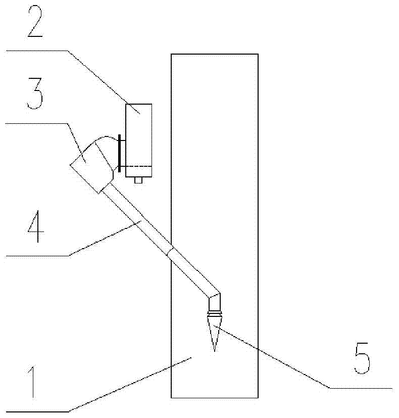
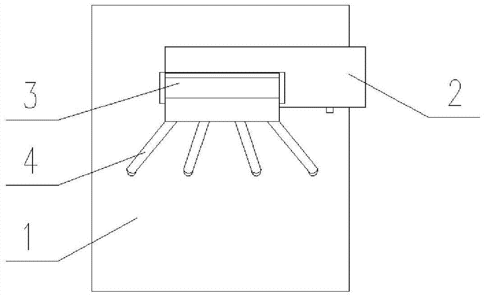
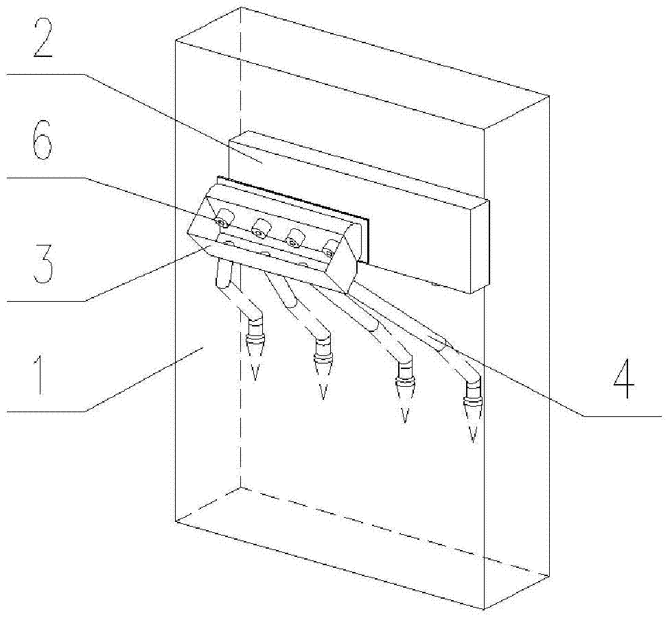
[0021] figure 1 Schematic diagram of the structure of the distributing device provided by this application; figure 2 for figure 1 left view of image 3 for figure 1 axonometric draw...


PUM


Abstract

The material distributing device provided by this application includes an ash hopper. The ash hopper is provided with a connecting end connected to the lower part of the side wall of the conveying chute. An adjustment mechanism that can adjust the opening of the conveying chute is arranged in the connecting end. The bottom of the ash hopper is also It is connected with a cloth end, and the cloth end is arranged inclined downward, and the end of the cloth end is arranged in the ascending flue. The ash hopper communicates with the lower part of the side wall of the conveying chute through the connecting end. The powder in the conveying chute will flow into the ash hopper under the action of gravity, and then the powder in the ash hopper will continue to be affected by gravity and flow from the cloth end to the ascending flue. There is an adjusting mechanism capable of adjusting the opening degree in the connecting end, so that a material distributing device capable of adjusting the feeding amount is provided. The present application also provides a dust collector including the above cloth distribution device.

Description

technical field [0001] The present application relates to the technical field of dust collector equipment, and more specifically, relates to a cloth distribution device. The present application also relates to a dust collector comprising the above cloth distribution device. Background technique [0002] At present, the purification method of electrolytic aluminum flue gas in China is generally a dry purification method using alumina adsorption. In order to ensure a high purification efficiency of alumina, how to add alumina evenly to the exhaust pipe of the purification system and flue gas Thorough mixing is crucial. [0003] At present, most of the feeding methods of electrolytic aluminum flue gas purification systems use VRI reactors. This feeding method uses high-pressure air to spray alumina into the ascending flue, which has disadvantages such as complex structure, high alumina damage rate, and uneven mixing. In the prior art, the blanking cannot be adjusted, and the ...

Claims


Application Information

Patent Timeline
Patent Type & Authority Patents(China)
IPC IPC(8): C25C3/22B01D53/02
CPCC25C3/22
Inventor 李威陈高强李军秀桑海波李金超
Owner HENAN KDNEU INT ENG
Learn More