
Yarn cylinder set dust-collection apparatus

A technology of vacuuming device and yarn bobbin, which is applied in textile and papermaking, etc., can solve the problems of not being able to avoid dust returning, having potential safety hazards, and being difficult to clean thoroughly, achieving good vacuuming effect, simplification of structure and work. The effect of space closure

Inactive Publication Date: 2015-10-07
XINCHANG COUNTY LANXIANG MACHINERY
View PDF0 Cites 3 Cited by
  • Summary
  • Abstract
  • Description
  • Claims
  • Application Information

AI Technical Summary

Problems solved by technology

The traditional dust collection device is located above the corresponding textile machinery, including a dust collection hood, a suction fan and a filter structure connected to the dust collection cover. During operation, the dust fluff generated below is sucked into the filter structure by the dust collection hood through the suction fan. In order to clean the environment around the dust-producing textile machinery, but because the environment of the dust collection hood of the dust collection device is an open environment, it is difficult to clean thoroughly
In addition, the filter structure usually consists of filter bag and filter plate. The filter bag is usually a cloth bag, which has poor air permeability, which not only has potential safety hazards, but also easily causes dust flocs to return from the filter structure to the dust collection pipe or dust collection cover. Dust phenomenon, although the filter plate has good air permeability, it cannot avoid dust return well

Method used

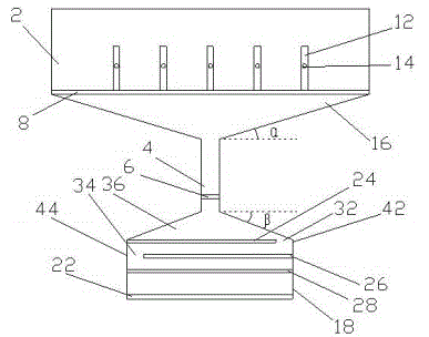
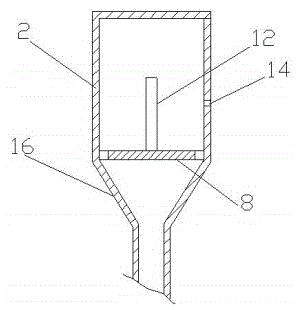

Image

  • Yarn cylinder set dust-collection apparatus
  • Yarn cylinder set dust-collection apparatus
  • Yarn cylinder set dust-collection apparatus

Examples


Embodiment Construction

[0012] The present invention will be further explained below in conjunction with the drawings in the specification:

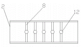
[0013] As shown in Figures 1-3, the present invention includes an elongated dust collecting hood 2, a dust filtering structure communicating with the dust collecting hood 2 through a dust collecting pipe 4, and a suction fan 6 arranged in the dust collecting pipe 4. The dust collecting hood 2 is provided with a yarn bobbin holder 8 and five yarn bobbin vertical shafts 12, and a yarn outlet hole 14 is opened on the side wall of the dust collecting hood 2. The diameter of the yarn outlet hole 14 is 1-3 mm. The dust collecting hood 2 includes a rectangular parallelepiped hollow body and a first funnel portion 16 provided at the bottom end of the dust collecting hood 2. One end of the large opening of the first funnel portion 16 is facing the inner cavity of the dust collecting hood 2, and one end of the small opening is connected with the dust collecting pipe 4. Th...


PUM


Abstract

The invention relates to a yarn cylinder set dust-collection apparatus characterized by comprising a long-stripped dust collection cover, a dust filtering structure communicated with the dust collection cover via a dust collection pipe and a suction ventilator disposed in the dust collection pipe. A yarn cylinder rack and a plurality of yarn cylinder vertical shafts are placed in the dust collection cover; a yarn outlet hole is formed in the side wall of the dust collection cover; and the dust filtering structure comprises a case type housing with one opened end, at least two filtration plates parallel to each other and disposed in the housing, and an air-out net arranged in the opened end of the housing. The dust collection range of the yarn cylinder set dust collection apparatus can cover the whole yarn cylinder set; work space is sealed, so great dust collection effect is achieved; and with the yarn cylinder rack and the yarn cylinder vertical shafts, cooperation with other yarn cylinder fixing device can be avoided, so a structure is simplified and convenient installation is realized.

Description

Technical field [0001] The invention relates to a dust collection device for a yarn drum group. Background technique [0002] In the textile field, yarns will produce more or less dust, including cotton dust and flying flowers, during the various production processes, which will affect the quality of textiles and pollute the workshop environment. The traditional dust suction device is installed above the corresponding textile machinery, including a dust collecting hood, a suction fan and a filter structure connected to the dust collecting hood. When working, the dust flocculant generated below is sucked into the filtering structure by the dust collecting hood through the suction fan. Thus, the environment around the dust-producing textile machine is cleaned, but since the environment facing the dust collecting hood of the dust suction device is an open environment, it is difficult to clean thoroughly. In addition, the filter structure usually consists of two kinds of filter bags...

Claims


Application Information

Patent Timeline
IPC IPC(8): D01H11/00
Inventor 石勇强
Owner XINCHANG COUNTY LANXIANG MACHINERY
Learn More