Floor brush of dust collector

A technology of vacuum cleaners and plastic casings, applied in the direction of suction nozzles, etc., can solve the problems of poor dust collection effect, and achieve the effect of high work efficiency, good dust collection effect and simple structure

Inactive Publication Date: 2017-06-20
余姚市金星网板厂
View PDF0 Cites 0 Cited by
  • Summary
  • Abstract
  • Description
  • Claims
  • Application Information

AI Technical Summary

Problems solved by technology

[0004] The problem to be solved by the present invention is to provide a floor brush for

Method used


Image

  • Floor brush of dust collector

Examples


Example Embodiment

[0011] The specific embodiments of the present invention will be described in further detail below in conjunction with the drawings and embodiments. The following examples are used to illustrate the present invention, but not to limit the scope of the present invention.

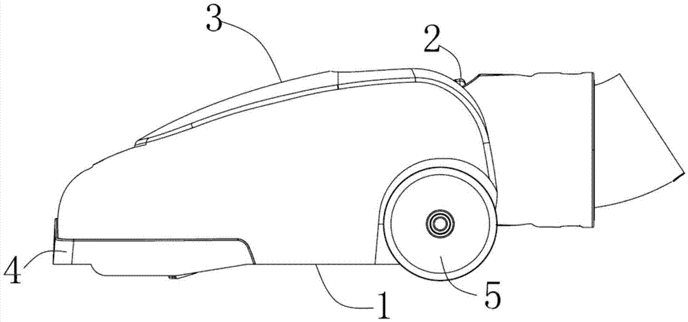
[0012] Such as figure 1 As shown, a vacuum cleaner floor brush of the present invention includes a plastic case 1, a buckle 2, an end cover 3, a plug 4, and a roller 5. The plastic case 1 is connected to the buckle 2, and the plastic case 1 The other end is matched with the buckle 2 and is connected with the end cap 3 in a sealed screw thread; the plug 4 is arranged in the internal cavity of the plastic case 1, and one end of the plug 4 is connected to the inlet of the suction port bottom plate. The air channel is in communication, and the other end is in communication with the plastic case 1; the rollers 5 are arranged on both sides of the upper cover; the bottom of the plastic case 1 is fixed with a pressure ...


PUM


Abstract

The invention provides a vacuum cleaner floor brush, which includes a plastic case, a buckle, an end cover, a plug and a roller; the plastic case is connected to the buckle, and the other end of the plastic case is matched with the buckle and is The end cover is sealed and threaded; the plug is arranged in the inner cavity of the plastic case, and one end of the plug communicates with the air inlet channel of the bottom plate of the dust suction port, and the other end communicates with the plastic case; the roller It is arranged on both sides of the upper cover; a pressure reducing valve is fixed on the bottom of the plastic case. The invention has the advantages of simple structure, good dust suction effect and high working efficiency.

Description

technical field [0001] The invention relates to a brush for a vacuum cleaner. Background technique [0002] Vacuum cleaners are widely used in daily life. The working principle of the vacuum cleaner is to use the motor to drive the blades to rotate at high speed, generate air negative pressure in the sealed housing, and suck dust. The floor brush of the existing vacuum cleaner has a poor dust collection effect. Contents of the invention [0003] (1) Technical problems to be solved [0004] The problem to be solved by the present invention is to provide a floor brush for a vacuum cleaner to overcome the defect of poor dust suction effect in the prior art. [0005] (2) Technical solutions [0006] In order to solve the above technical problem, the present invention provides a vacuum cleaner brush, which includes a molded case, a buckle, an end cap, a plug and a roller; the molded case is connected to the buckle, and the other end of the molded case is connected to the T...

Claims


Application Information

Patent Timeline
IPC IPC(8): A47L9/02
CPCA47L9/02
Inventor 童均苗
Owner 余姚市金星网板厂
Why Eureka
Try Eureka