Vapour liquid separator for heat pump system

A vapor-liquid separator and heat pump system technology, applied in refrigeration and liquefaction, lighting and heating equipment, compressors, etc., can solve the problems of compressor refrigeration system damage, liquid shock, liquid refrigerant entry, etc. Liquid-liquid hammer phenomenon, the effect of improving safety and reliability

Inactive Publication Date: 2015-10-07
CHONGQING MIDEA GENERAL REFRIGERATING EQUIP +1
View PDF7 Cites 4 Cited by
  • Summary
  • Abstract
  • Description
  • Claims
  • Application Information

AI Technical Summary

Problems solved by technology

When the amount of liquid refrigerant exceeds the upper critical point of the U-tube, a large amount of liquid refrigerant will enter the compressor when the unit is turned on, causing serious liquid shock phenomenon, which will cause great damage to the compressor itself and the refrigeration system

Method used


Image

  • Vapour liquid separator for heat pump system
  • Vapour liquid separator for heat pump system

Examples


Embodiment Construction

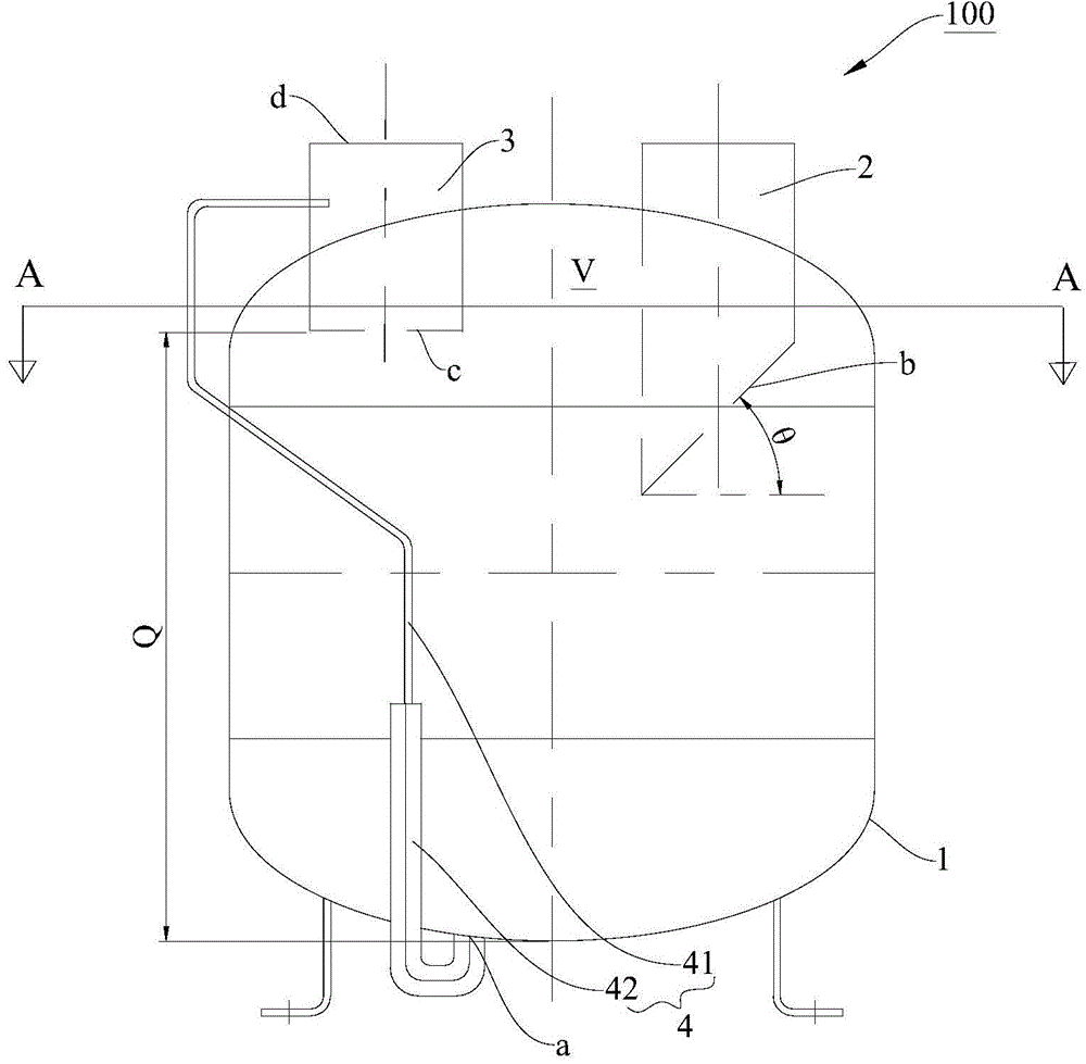
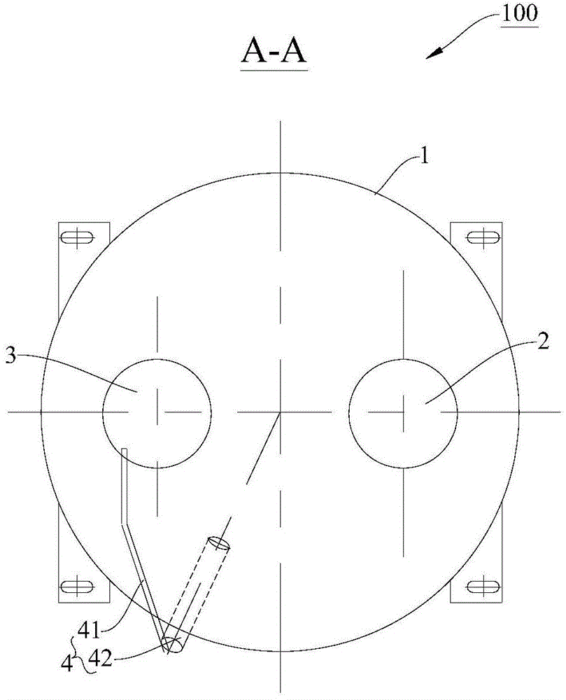
[0025] Embodiments of the present invention are described in detail below, examples of which are shown in the drawings, wherein the same or similar reference numerals designate the same or similar elements or elements having the same or similar functions throughout. The embodiments described below by referring to the figures are exemplary and are intended to explain the present invention and should not be construed as limiting the present invention.

[0026] In describing the present invention, it is to be understood that the terms "center", "height", "upper", "lower", "vertical", "horizontal", "top", "bottom", "inner", The orientation or positional relationship indicated by "outer", "clockwise", "counterclockwise", "axial", "radial", "circumferential" etc. is based on the orientation or positional relationship shown in the drawings, and is only for It is convenient to describe the present invention and simplify the description, but does not indicate or imply that the device o...


PUM


Abstract

The invention discloses a vapour liquid separator for a heat pump system. The vapour liquid separator comprises a shell, an inlet pipe, an outlet pipe and an oil return pipe. A containing cavity is defined in shell, and an oil return opening is formed in the shell. The inlet pipe is arranged on the upper portion of the shell. The outlet pipe is arranged at the top of the shell. A first end of the outlet pipe stretches into the containing cavity. The portion, stretching into the containing cavity, of the outlet pipe is a straight pipe. The oil return pipe is connected with the oil return opening and the outlet pipe. At least one part of the oil return pipe forms a capillary tube. According to the vapour liquid separator for the heat pump system, a great amount of liquid refrigerants in the vapour liquid separator are prevented from entering a compressor, meanwhile it is further avoided that the heat pump system generates the liquid impact phenomenon after defrosting is ended, the liquid impact phenomenon with liquid generated after the heat pump system is halted and when the heat pump system is restarted is further avoided, and the safety and stability of the heat pump system with the vapour liquid separator and the compressor connected with the vapour liquid separator are improved.

Description

technical field [0001] The invention relates to the field of heat pump systems, in particular to a gas-liquid separator used in the heat pump system. Background technique [0002] The gas-liquid separator used in the heat pump system usually has a U-shaped outlet pipe, and there are still some shortcomings and deficiencies in use, as follows: [0003] a. When the heat pump unit is in reverse cycle defrosting, a large amount of liquid refrigerant is condensed and stored inside the fin heat exchanger. After the defrosting is completed, the refrigerant flow path is switched, and a large amount of stored liquid refrigerant will enter the vapor-liquid separator . When the amount of liquid refrigerant exceeds a certain range, the liquid refrigerant will directly enter the U tube inlet, causing the compressor to inhale a large amount of liquid refrigerant, causing serious liquid shock, which will cause great damage to the compressor itself and the refrigeration system; [0004] b...

Claims


Application Information

Patent Timeline
Patent Type & Authority Applications(China)
IPC IPC(8): F25B43/00
CPCF25B31/002F25B43/00F25B41/37
Inventor 代斌
Owner CHONGQING MIDEA GENERAL REFRIGERATING EQUIP
Why Eureka
Try Eureka