Air conditioner and air conditioner condensation-prevention method

An air conditioner and anti-condensation technology, which is applied in the prevention of condensed water, air-conditioning systems, heating methods, etc., can solve the problems of condensed water, customer inconvenience, etc., and achieve the effect of avoiding liquid shock

Active Publication Date: 2019-11-08
广州市雷子克电气机械有限公司
View PDF7 Cites 2 Cited by
  • Summary
  • Abstract
  • Description
  • Claims
  • Application Information

AI Technical Summary

Problems solved by technology

[0002] Ordinary air conditioners will produce condensed water at the evaporator during use, which will cause inconvenience to customers, and in some specific environments, they need to be kept dry

Method used


Image

  • Air conditioner and air conditioner condensation-prevention method
  • Air conditioner and air conditioner condensation-prevention method
  • Air conditioner and air conditioner condensation-prevention method

Examples


no. 1 example

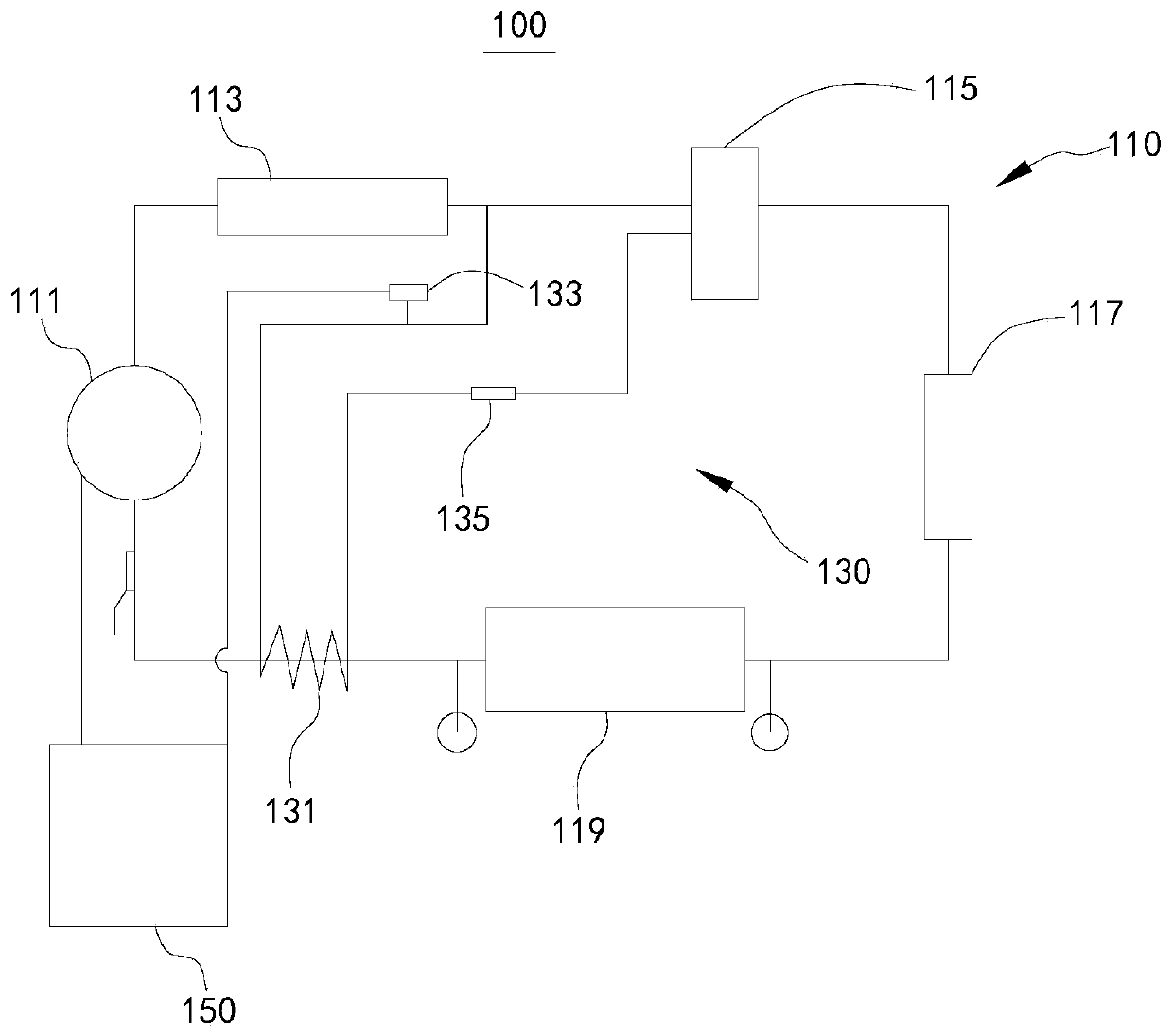
[0052] Please refer to figure 1 As shown, the air conditioner 100 provided in this embodiment can prevent the occurrence of liquid hammer phenomenon while preventing condensation water from being generated at the evaporator 119 .

[0053] The air conditioner provided in this embodiment includes a circulation loop 110, a heat recovery branch 130 and a controller 150. The circulation loop 110 is provided with a variable frequency compressor 111, a condenser 113, a liquid storage tank 115, an electronic expansion valve 117 and an evaporator in sequence. The output end of the evaporator 119 is directly connected to the input end of the inverter compressor 111 . That is, in the actual working process, the variable frequency compressor 111 outputs the high-temperature and high-pressure gaseous refrigerant to the condenser 113 to release heat, condenses into a medium-temperature and high-pressure liquid state, and then enters the liquid storage tank 115, and then is throttled through...

no. 2 example

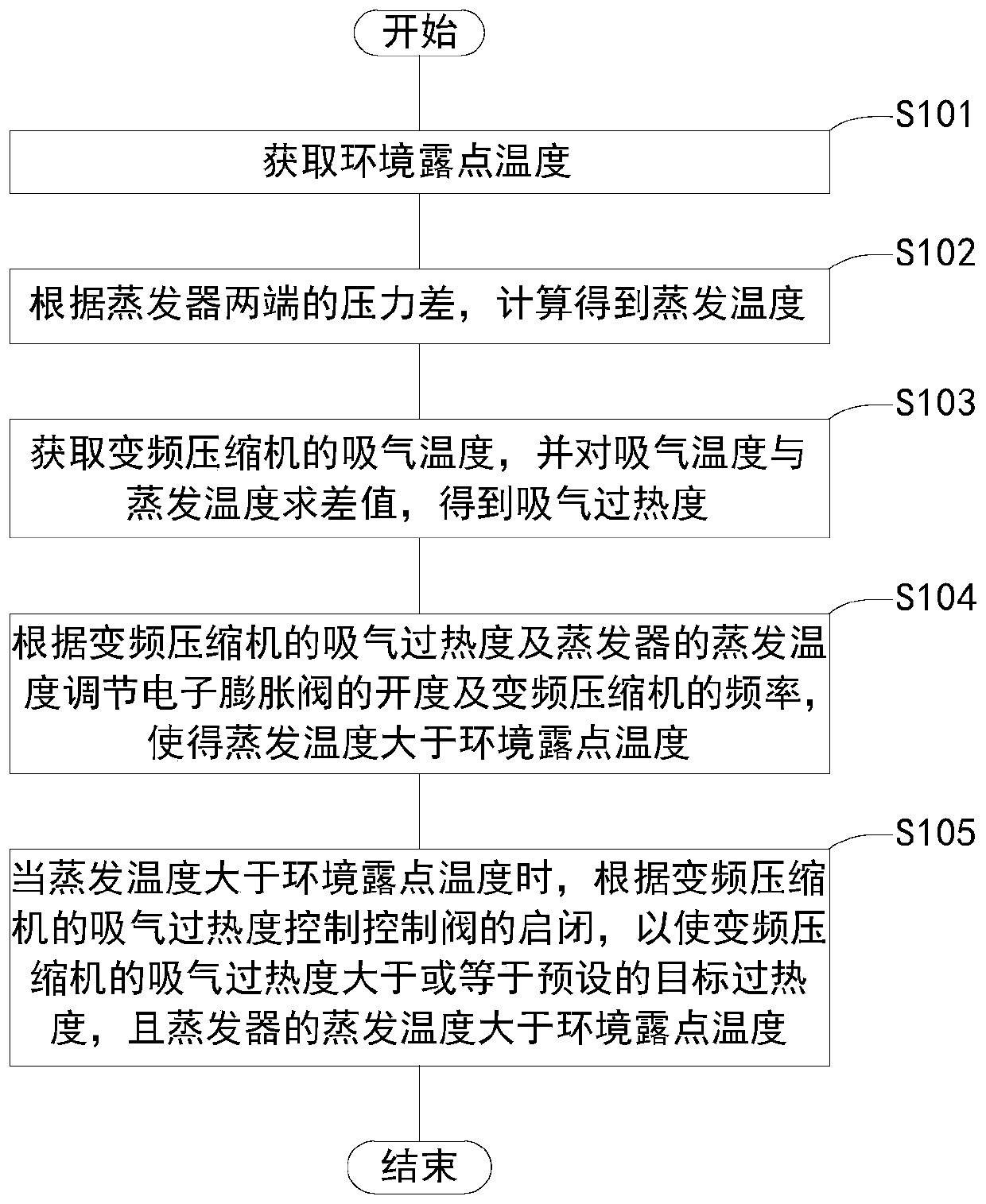
[0062] figure 2 For a schematic block diagram of the process flow of the air conditioner anti-condensation method for the air conditioner 100 provided in this embodiment, please refer to figure 2 As shown, the anti-condensation method of the air conditioner includes:

[0063] Step S101, obtaining the ambient dew point temperature.

[0064] After the air conditioner 100 is turned on, the controller 150 obtains the temperature and humidity of the indoor environment through the temperature and humidity sensor, and then calculates the ambient dew point temperature.

[0065] Further, the anti-condensation method for the air conditioner may also include:

[0066] Step S102, calculating the evaporation temperature according to the pressure difference between the two ends of the evaporator.

[0067] The controller 150 receives the refrigerant pressure detected by the pressure sensors at both ends of the evaporator 119, performs an average calculation to obtain the evaporation pre...


PUM


Abstract

The invention discloses an air conditioner and an air conditioner condensation-prevention method, and relates to the technical field of air conditioners. The air conditioner comprises a backheating branch and a controller; the controller is electrically connected with a frequency conversion compressor and an electronic expansion valve, and is used for adjusting the opening degree of the electronicexpansion valve and the frequency of the frequency conversion compressor according to the air suction overheat degree of the frequency conversion compressor and the evaporation temperature of an evaporator, and therefore the evaporation temperature is larger than the environment dew point temperature. One end of the backheating branch is connected with a pipeline enabling a condenser to be connected with a liquid storage tank, the other end of the backheating branch is connected with the liquid storage tank, the backheating branch is provided with a backheating pipe segment and a control valve, the control valve is electrically connected with a controller, the backheating pipe segment is wound on the pipeline between the evaporator and the frequency conversion compressor, and is used forcarrying out heat exchange on a refrigerant before entering the frequency conversion compressor from the evaporator. The liquid hammer phenomenon is avoided while in the work process the evaporator ofthe air conditioner does not generate condensate water.

Description

technical field [0001] The present invention relates to the technical field of air conditioners, and in particular, to an air conditioner and an anti-condensation method for the air conditioner. Background technique [0002] Ordinary air conditioners will produce condensed water at the evaporator during use, which brings inconvenience to customers, and needs to be kept dry in some specific environments. [0003] Therefore, there is an urgent need for an air conditioner that does not generate condensed water at the evaporator during use. SUMMARY OF THE INVENTION [0004] The object of the present invention is to provide an air conditioner which can prevent condensation water from being generated at the evaporator during use. [0005] Another object of the present invention is to provide an anti-condensation method for an air conditioner, which can prevent condensed water from being generated at the evaporator during the use of the air conditioner. [0006] The present inv...

Claims


Application Information

Patent Timeline
Patent Type & Authority Applications(China)
IPC IPC(8): F24F5/00F24F11/89F24F11/86F24F11/84F24F11/64F24F11/30F24F13/22
CPCF24F5/001F24F13/22F24F2013/221F24F11/30F24F11/64F24F11/84F24F11/86F24F11/89
Inventor 林威
Owner 广州市雷子克电气机械有限公司
Why Eureka
Try Eureka