Multi-pressure-stage air supply type high-temperature heat pump steam system

A high-temperature heat pump and steam system technology, applied in heat pumps, steam generation, steam generation methods, etc., can solve problems such as isentropic efficiency, low performance parameters of volumetric efficiency, immature research on high-temperature heat pump systems, and reduced service life of compressors. To achieve the scope of application of green environmental protection, improve efficiency and income, and achieve the effect of efficient production

Active Publication Date: 2020-10-30
CHINA UNIV OF PETROLEUM (EAST CHINA) +1
View PDF6 Cites 1 Cited by
  • Summary
  • Abstract
  • Description
  • Claims
  • Application Information

AI Technical Summary

Problems solved by technology

[0002] With the application of heat pump technology more and more widely, people hope to use it in the field of steam production. Therefore, the heating temperature requirements of the heat pump system are gradually increased, resulting in an increase in the pressure ratio of the system compressor under this working condition. However, at this stage The research on high-temperature heat pump systems is relatively immature, especially the traditional heat pump system is still used in the research of large pressure ratio conditions, so that the performance parameters such as isentropic efficiency and volumetric efficiency of the compressor in the heat pump system under high pressure ratio conditions are relatively immature. Low, the heating performance of the system is not ideal. In addition, when the condensing temperature is too high, the refrigerant used in the working process is prone to liquid shock to the compressor, which greatly reduces the service life of the compressor.

Method used


Image

  • Multi-pressure-stage air supply type high-temperature heat pump steam system
  • Multi-pressure-stage air supply type high-temperature heat pump steam system
  • Multi-pressure-stage air supply type high-temperature heat pump steam system

Examples


Embodiment Construction

[0021] In order to make the object, technical solution and advantages of the present invention more clear, the present invention will be further described in detail below in conjunction with the examples. It should be understood that the specific embodiments described here are only used to explain the present invention, and are not intended to limit the present invention, that is, the described embodiments are only some of the embodiments of the present invention, but not all of the embodiments.

[0022] The present invention will be further described below in conjunction with accompanying drawing:

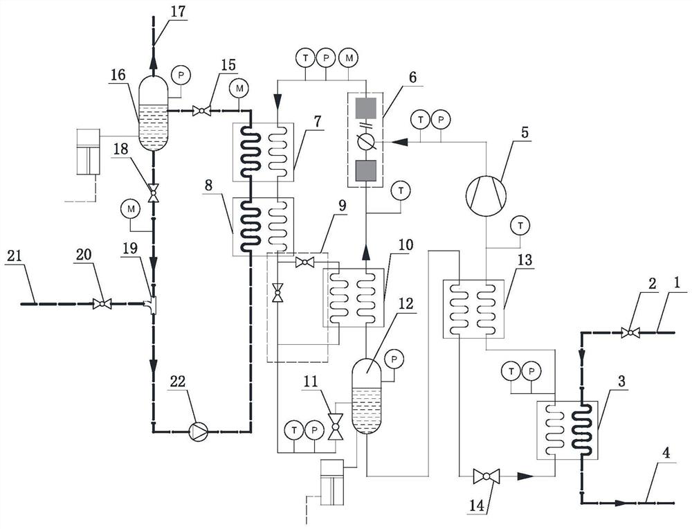
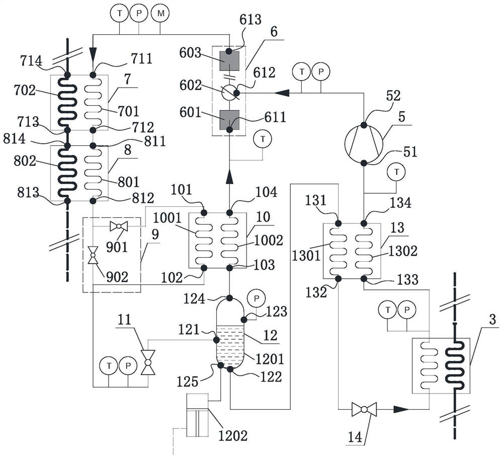
[0023] Such as figure 1 As shown, a multi-pressure level air-supplementing high-temperature heat pump steam system, the high-temperature heat pump steam system is composed of a heat supply source module, a high-temperature heat pump cycle module and an evaporation module, and the heat supply source module, high-temperature heat pump cycle module and evaporation The module consist...


PUM


Abstract

The invention relates to a multi-pressure-stage air supply type high-temperature heat pump steam system, and belongs to the field of application expansion of high-temperature heat pump systems. The heat pump steam system is composed of assemblies such as a heat source inlet, a heat source throttle valve, an evaporator, a heat source outlet, an air supply compressor, a main body compressor, a condenser, a heat return control valve group, a first heat regenerator, a subcooler, a primary expansion valve, a primary flash evaporator, and a secondary flash evaporator. Through multi-stage pressure regulation and control in the system, the heating effect and the steam production efficiency of the system are effectively improved, and a high-temperature heat pump circulation module partially adoptsfour-stage pressure comprising low pressure, medium pressure, high pressure and air supply pressure, so that the working state of a circulation refrigerant is effectively controlled, the power consumption of a compressor inside the system is reduced, the heating effect of the system is improved, the steam production efficiency is improved, and the structural optimization of the high-temperature heat pump system and the further development of the field of heat pump steam production are facilitated.

Description

technical field [0001] The invention relates to a high-temperature heat pump steam system, in particular to a multi-pressure stage air-supplementing high-temperature heat pump steam system. Background technique [0002] With the application of heat pump technology more and more widely, people hope to use it in the field of steam production. Therefore, the heating temperature requirements of the heat pump system are gradually increased, resulting in an increase in the pressure ratio of the system compressor under this working condition. However, at this stage The research on high-temperature heat pump systems is relatively immature, especially the traditional heat pump system is still used in the research of large pressure ratio conditions, so that the performance parameters such as isentropic efficiency and volumetric efficiency of the compressor in the heat pump system under high pressure ratio conditions are relatively immature. Low, the heating performance of the system i...

Claims


Application Information

Patent Timeline
IPC IPC(8): F25B30/02F25B31/00F25B39/02F25B40/02F22B1/00
CPCF25B30/02F25B31/00F25B39/02F25B40/02F22B1/00
Inventor 张彦廷张晧徐敬玉王林李斌黄峥张林赵晓光
Owner CHINA UNIV OF PETROLEUM (EAST CHINA)
Why Eureka
Try Eureka