
Air conditioning system and compressor

A technology for air conditioning systems and compressors, which is applied in the directions of compressors, compressors, and irreversible cycle compressors, etc., and can solve problems such as the deviation of secondary compression from the isentropic compression process, the increase of compressor power consumption, and the increase of exhaust temperature. , to achieve the effect of reducing power consumption, reducing exhaust temperature and preventing liquid hammer phenomenon

Active Publication Date: 2018-02-09
GREE ELECTRIC APPLIANCES INC +1
View PDF9 Cites 2 Cited by
  • Summary
  • Abstract
  • Description
  • Claims
  • Application Information

AI Technical Summary

Problems solved by technology

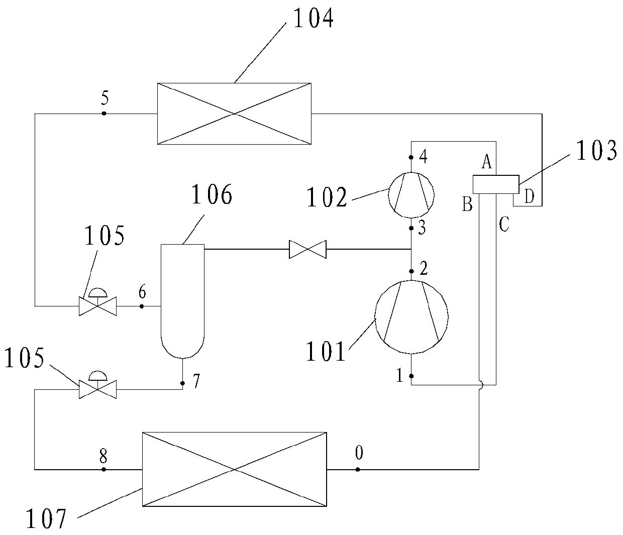
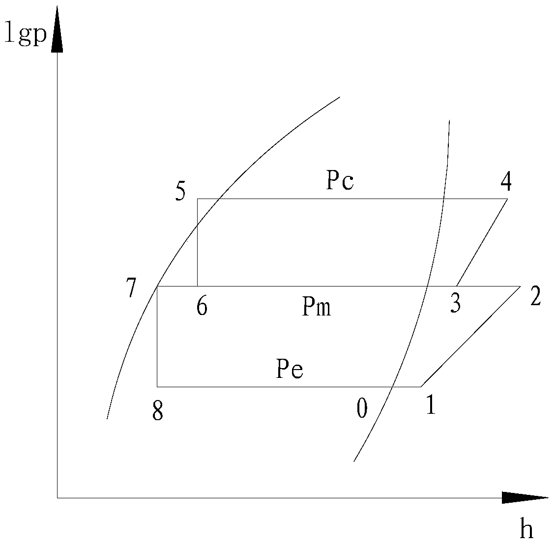
Since the suction of the two-stage compression (status point 3) is in an overheated state, it will cause the two-stage compression to deviate from the isentropic compression process, which will increase the power consumption of the compressor and increase the exhaust temperature
In addition, in system matching, due to differences in refrigerant charge and operating conditions, the suction state of the high-pressure compressor 101 may be in a full liquid state or a gas-liquid mixed state, which may easily cause compressor liquid shock

Method used


Image

  • Air conditioning system and compressor
  • Air conditioning system and compressor
  • Air conditioning system and compressor

Examples


Embodiment Construction

[0028] In order to make the object, technical solution and advantages of the present invention clearer, the air conditioning system and compressor of the present invention will be further described in detail below in conjunction with the accompanying drawings and embodiments. It should be understood that the specific embodiments described here are only used to explain the present invention, not to limit the present invention.

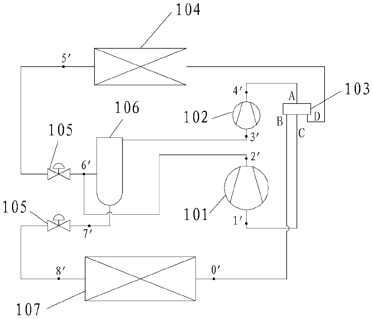
[0029] refer to Figure 3 to Figure 5 , an embodiment of the air conditioning system of the present invention includes a compressor, a condenser 104, a first throttling device (not shown), a flash evaporator 106 and an evaporator 107, the compressor, the condenser 104, a first throttling device, a flash The evaporator 106 and the evaporator 107 are connected in sequence to form a refrigeration cycle. The compressor includes a low-pressure stage compressor 101 and a high-pressure stage compressor 102. The suction end of the low-pressure stage compressor ...


PUM


Abstract

The present invention provides an air conditioning system, comprising a compressor, a condenser, a first throttling device, a flash evaporator and an evaporator, and the compressor, the condenser, the first throttling device, the flash evaporator and the evaporator are connected in sequence to form a refrigeration cycle , the compressor includes a low-pressure stage compressor and a high-pressure stage compressor, the suction end of the low-pressure stage compressor is connected to the first port of the evaporator, the second port of the evaporator is connected to the second port of the flasher, and the first port of the flasher The first throttling device in series is connected to the first port of the condenser, the second port of the condenser is connected to the exhaust end of the high-pressure stage compressor, and the suction end of the high-pressure stage compressor is connected to the third port of the flasher; the low-pressure stage compressor The exhaust end of the outlet is connected to the first port of the flasher or to the third port of the flasher or to the fourth port of the flasher. It also relates to a compressor. It makes the two-stage compression closer to the isentropic compression process and avoids the liquid hammer phenomenon of the compressor.

Description

technical field [0001] The invention relates to the refrigeration field, in particular to an air conditioning system and a compressor. Background technique [0002] Existing conventional two-stage enthalpy-enhancing compressors are used in air-conditioning systems, such as figure 1 As shown, the air conditioning system includes a high-pressure compressor 101, a low-pressure compressor 102, a four-way valve 103, a condenser 104, a stop valve 105, a flash evaporator 106, and an evaporator 107. The low-pressure compressor 102 compresses (one-stage compression) The final superheated steam (state point 2) is mixed with the saturated steam (state point 6) drawn from the flash evaporator 106, and the mixed state is a superheated state, and enters the suction end of the high-pressure stage compressor 101 (two-stage compression), and the air conditioner The lgp-h diagram of the system in cooling operation is as follows figure 2 Shown, where the numbers 0, 2, 3, 4, 5, 6, 7, 8 repre...

Claims


Application Information

Patent Timeline
Patent Type & Authority Patents(China)
IPC IPC(8): F25B1/10F25B41/04F25B41/06F25B31/00F25B41/20F25B41/34F25B41/37
CPCF25B1/10F25B31/00F25B2500/00F25B2313/02741F25B41/34F25B41/37F25B41/20F25B41/31Y02B30/70
Inventor 徐嘉梁志礼胡余生蔡青
Owner GREE ELECTRIC APPLIANCES INC
Learn More