Device and method for optical rotation measurement by elastic optical modulation

A technology of elastic light modulation and light beam, which is applied in the direction of instruments, can solve the problems of expensive experiment cost, inconvenient industrial integration, and inability to simultaneously acquire and observe data of multiple frequency multiplied signal channels, so as to achieve good modulation stability and benefit Industrial automation integration application, the effect of eliminating common mode noise

Inactive Publication Date: 2018-07-06
ZHONGBEI UNIV
View PDF3 Cites 0 Cited by
  • Summary
  • Abstract
  • Description
  • Claims
  • Application Information

AI Technical Summary

Problems solved by technology

The literature [Highfrequency polarization modulation method for measuring optical rotation[J],Applied Optics,1975,14(3):761-764] was the first to propose the use of elasto-optic modulation method to measure optical rotation. In 1998, B L Wang from Hinds Company in the United States realized The optical rotation measurement with a sensitivity of 0.001° [see literature: Measurement of circular and linear birefringence using the photoelastic modulator [J], Proc. of SPIE, 1999, 3535: 294-301], but the above methods all use an analog lock-in amplifier to To obtain optical rotation data, it is impossible to obtain and observe data of multiple frequency-doubling signal channels at the same time, the experimental cost is expensive, and it is not easy for industrial integration

Method used


Image

  • Device and method for optical rotation measurement by elastic optical modulation
  • Device and method for optical rotation measurement by elastic optical modulation
  • Device and method for optical rotation measurement by elastic optical modulation

Examples


Embodiment Construction

[0024] The following embodiments will further describe the present invention in conjunction with the accompanying drawings.

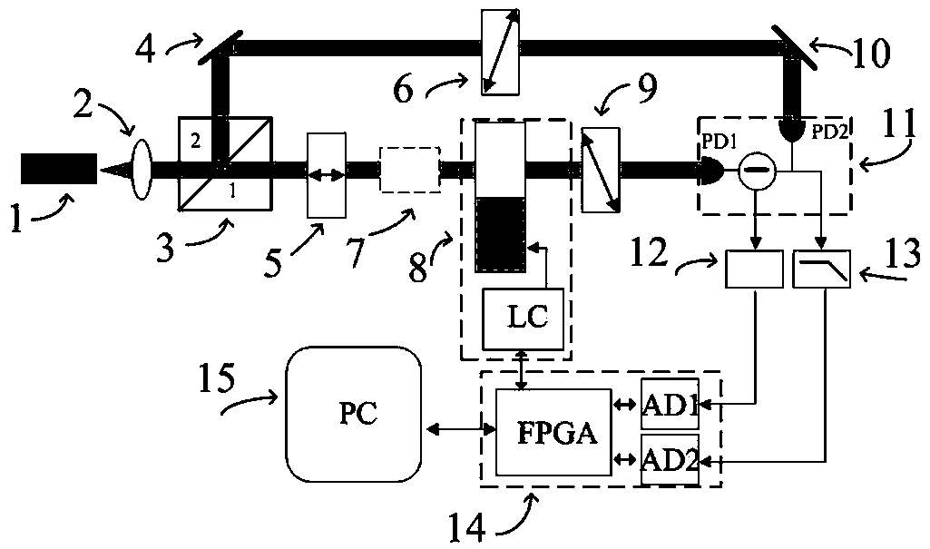
[0025] Such as figure 1 As shown, the detection laser 1 is expanded and collimated by the lens 2, and then divided into the first beam and the second beam by the polarization beam splitter prism 3, and the first beam passes through the polarizer 5, the optically rotating sample 7, and the elastic optical modulator 8 in sequence. And the analyzer 9 is detected by the first detector (PD1) to form a detection optical path, and the second light beam is incident on the second detector (PD2) through the first reflector 4 and the second reflector 10 to form a reference optical path. A polarizer 6 is inserted into the reference light path to adjust the reference light intensity; when the light intensity adjustment of the reference light path is the same as the DC light intensity of the detection light path, the differential balance detection module 11 outputs a...


PUM


Abstract

The invention relates to a device and method for measuring optical rotation by elastic optical modulation, which belongs to the field of application research of elastic optical polarization modulation; it provides a real-time, high-speed, high-precision and high-sensitivity optical rotation measuring device and method; the invention is based on elastic It is realized by optical polarization modulation technology, differential balance detection technology and digital phase-locked amplification technology. When the light intensity of the optical path and the detection optical path are the same, the differential output modulates the AC signal carrying the optical rotation information, and the detector outputs a DC signal. After the AC signal is pre-amplified, it is collected by AD and input to the FPGA to complete digital phase-locking. The DC signal is low-pass filtered. , collected by AD and input to FPGA, together with the digital phase-locked data, transmitted to the computer, and finally, the computer completes the optical rotation data processing, storage and display; the present invention is mainly used in the application of elasto-optical polarization modulation and optical rotation measurement.

Description

technical field [0001] The present invention relates to the field of application of optical polarization modulation and optical rotation measurement, more specifically, to a device and method for measuring optical rotation by elastic optical modulation, which is a real-time, high-speed, high-precision and high-sensitivity optical rotation measurement method . Background technique [0002] In recent years, the phenomenon of optical rotation and its application have been more and more widely studied. It is of great significance for the high-precision and high-sensitivity measurement of optical rotation in the fields of optical dispersion, optical absorption and magneto-optical rotation of materials. It is particularly worth pointing out that since the new generation of quantum-controlled magnetometer / inertial measurement device was successfully developed, the optical rotation measurement of the manipulated quantum directly determines the detection accuracy and sensitivity of t...

Claims


Application Information

Patent Timeline
Patent Type & Authority Patents(China)
IPC IPC(8): G01J11/00
Inventor 李晓王爽李克武王志斌王黎明张瑞李晋华张敏娟陈媛媛陈光威
Owner ZHONGBEI UNIV
Why Eureka
Try Eureka