Micro projector module and display device

A display device and micro-projection technology, applied in installation, optics, instruments, etc., can solve problems such as lack of diopter adjustment function, poor user experience for visually impaired users, and insufficient fine design of display devices, so as to improve user experience and ensure The effect of comfort and convenience upgrade

Active Publication Date: 2015-10-07
GEER TECH CO LTD
View PDF6 Cites 12 Cited by
  • Summary
  • Abstract
  • Description
  • Claims
  • Application Information

AI Technical Summary

Problems solved by technology

[0003] The present invention provides a micro-projection module and a display device to solve the problem that the design of the existing display device is not fine enough, and the lack of a diopter adjustment function leads to poor user experience for visually impaired users

Method used


Image

  • Micro projector module and display device
  • Micro projector module and display device
  • Micro projector module and display device

Examples


Embodiment 1

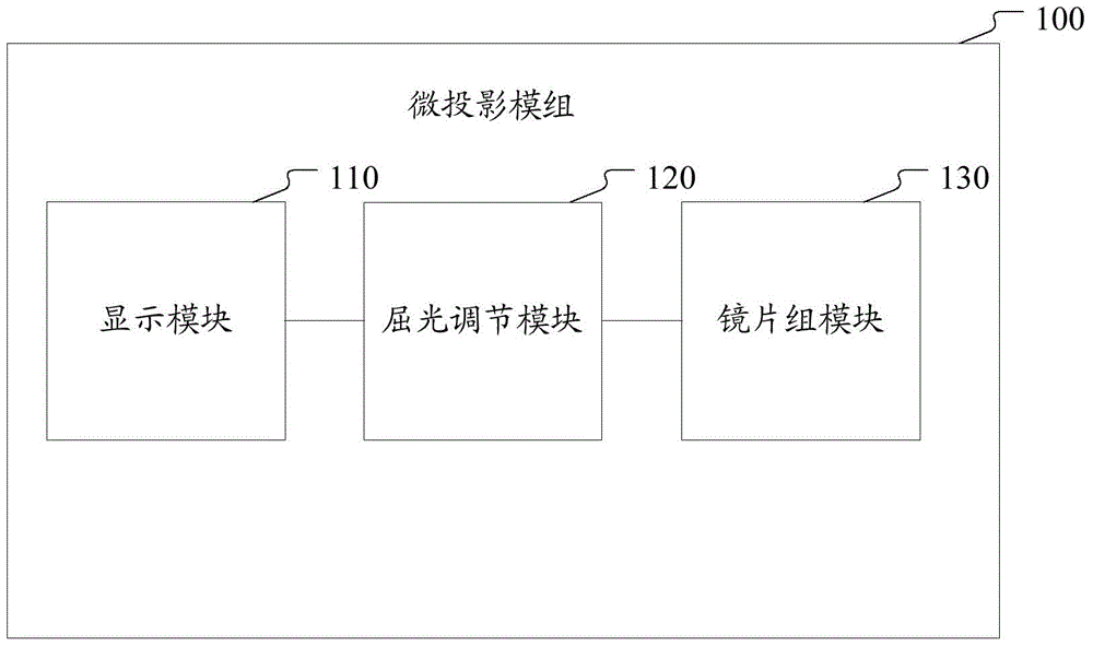
[0048] figure 1 is a block diagram of a micro-projection module according to an embodiment of the present invention, see figure 1 , the micro-projection module 100 of the present invention includes: a display module 110, a lens group module 130 and a refractive adjustment module 120;

[0049] The display module 110 includes a display unit and a display bracket for fixing the display unit, and the display unit is used for displaying input data;

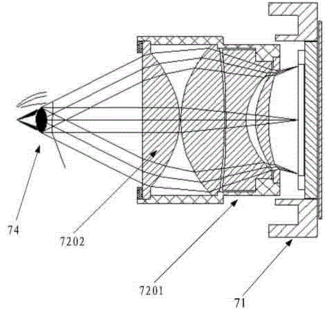
[0050] The lens group module 130 includes a group of lenses and a lens group bracket for fixing each lens, and a group of lenses is used to adjust the dioptric imaging of the light emitted by the display unit;

[0051] The diopter adjustment module 120 is connected to the display bracket and the lens group bracket, and is used to realize the linear reciprocating motion of the display module 110 relative to the lens group module 130 by using the cam principle.

[0052] figure 1 The shown micro-projection module realizes modular desig...

Embodiment 2

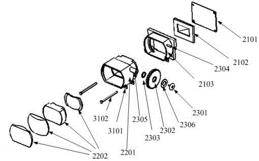
[0084] Figure 5 It is a schematic diagram of the overall structure of a micro-projection module according to another embodiment of the present invention, Figure 6a Yes Figure 5 A cross-sectional top view of a micro-projection module shown, see Figure 5 and Figure 6a , Using the cam principle, under the action of the spring, the ejector rod on the display bracket is always on the cam profile; with the rotation of the cam, the display bracket performs linear reciprocating motion relative to the lens group bracket. In this embodiment, the micro-projection module includes: a display module, a lens group module, and a refraction adjustment module: the display module includes a display bracket 51 , the lens group module includes a lens group bracket 52 , and the refraction adjustment module includes: a second knob 5302 , installation shaft 5301, knob bracket 5303, elastic member 5306, damping member 5307, cross bar 5305 and top block 5304;

[0085] The top block 5304 is set...


PUM


Abstract

The invention discloses a micro projector module and a display device. The micro projector module comprises a display module, a lens set module and a refraction adjusting module. The display module comprises a display unit and a fixing rack fixing the display unit, wherein the display unit is used for displaying input data. The lens set module comprises a set of lenses and a lens set rack used for fixing each lens, wherein the set of lenses are used for performing refractive imaging adjustment on light emitted by the display unit. The refraction adjusting module is in connection with the display rack and the lens set rack, and is used for allowing the display module to perform straight reciprocating motion relative to the lens set module by utilizing the cam principle. The micro projector module realizes modularization design and application, has the characteristics of concise and compact structure, and high precision, and is more comfortable to wear. In addition, the micro projector module also comprises a refraction adjusting mechanism which can rapidly and conveniently adjust refraction effects, so that users with farsightedness or shortsightedness can use the micro projector module without wearing glasses, thereby greatly improving user experience.

Description

technical field [0001] The present invention relates to the technical field of display devices, in particular to a micro-projection module and a display device. Background technique [0002] At present, the design of the display device is not precise enough, the structure is complex, and the volume is large, and most of the existing display devices are easy to use for users with normal vision, but inconvenient for users with visual impairments. It is often necessary to wear glasses before using the device, resulting in poor user experience for visually impaired users. SUMMARY OF THE INVENTION [0003] The present invention provides a micro-projection module and a display device, so as to solve the problems that the existing display device is not sufficiently finely designed and does not have the function of refraction adjustment, resulting in poor user experience for visually impaired users. [0004] In order to achieve the above object, the technical scheme of the presen...

Claims


Application Information

Patent Timeline
Patent Type & Authority Applications(China)
IPC IPC(8): G03B21/14G03B21/00
CPCG02B7/021G02B7/023G03B21/142G03B21/16
Inventor 张锋
Owner GEER TECH CO LTD
Why Eureka
Try Eureka