
Over-temperature protection circuit used for high-side power switch

A technology of over-temperature protection circuit and high-side power, which is applied in emergency protection circuit devices, emergency protection devices with automatic disconnection, circuit devices, etc. Problems such as the distance change of the upper surface and the inconsistency of the forming size and width can achieve the effect of stable working performance, preventing unstable opening and thermal shock

Active Publication Date: 2015-10-07
UNIV OF ELECTRONICS SCI & TECH OF CHINA
View PDF3 Cites 15 Cited by
  • Summary
  • Abstract
  • Description
  • Claims
  • Application Information

AI Technical Summary

Problems solved by technology

[0005] In view of the shortcomings of the prior art described above, the purpose of the present invention is to solve the problems of inconsistent forming dimension width and the change of the distance from the nozzle to the upper surface of the cladding layer in the existing GMA additive manufacturing, and to provide a GMA additive manufacturing double passive Visual sensing device and detection method thereof
[0006] In order to solve the defects that the traditional over-temperature protection scheme cannot be used in high-voltage environments such as high-side power switches and the thermal shutdown threshold point is easily affected by power supply voltage fluctuations, the present invention proposes an over-temperature protection for high-side power switch circuits protect the circuit

Method used


Image

  • Over-temperature protection circuit used for high-side power switch
  • Over-temperature protection circuit used for high-side power switch
  • Over-temperature protection circuit used for high-side power switch

Examples


Embodiment Construction

[0028] Embodiments of the present invention are described below through specific examples, and those skilled in the art can easily understand other advantages and effects of the present invention from the content disclosed in this specification. The present invention can also be implemented or applied through other different specific implementation modes, and various modifications or changes can be made to the details in this specification based on different viewpoints and applications without departing from the spirit of the present invention.

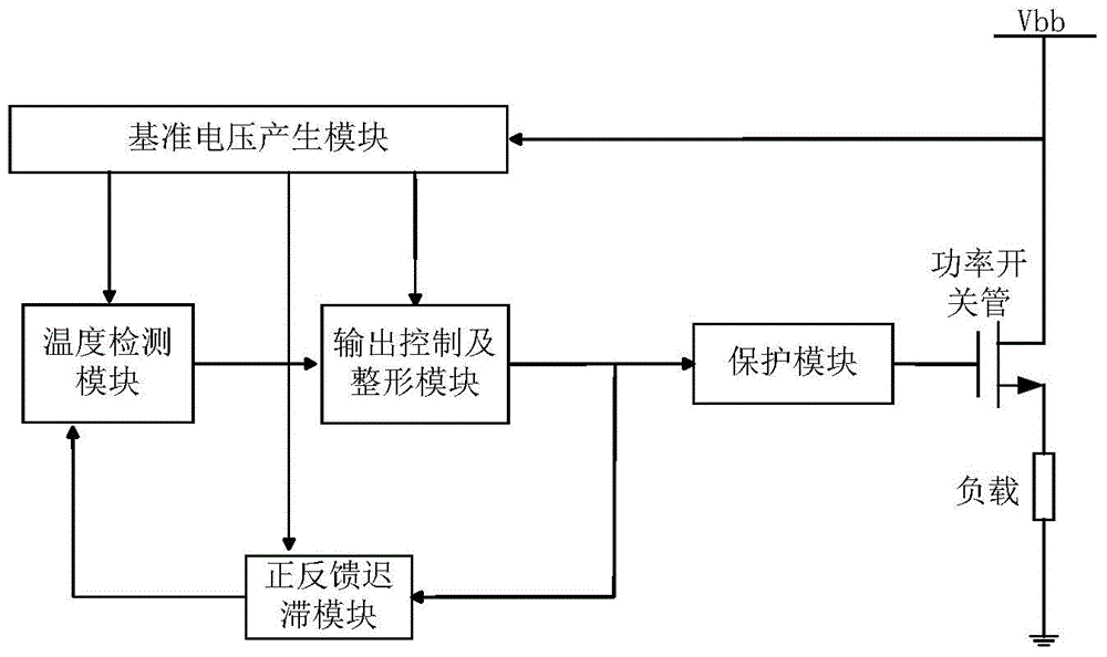
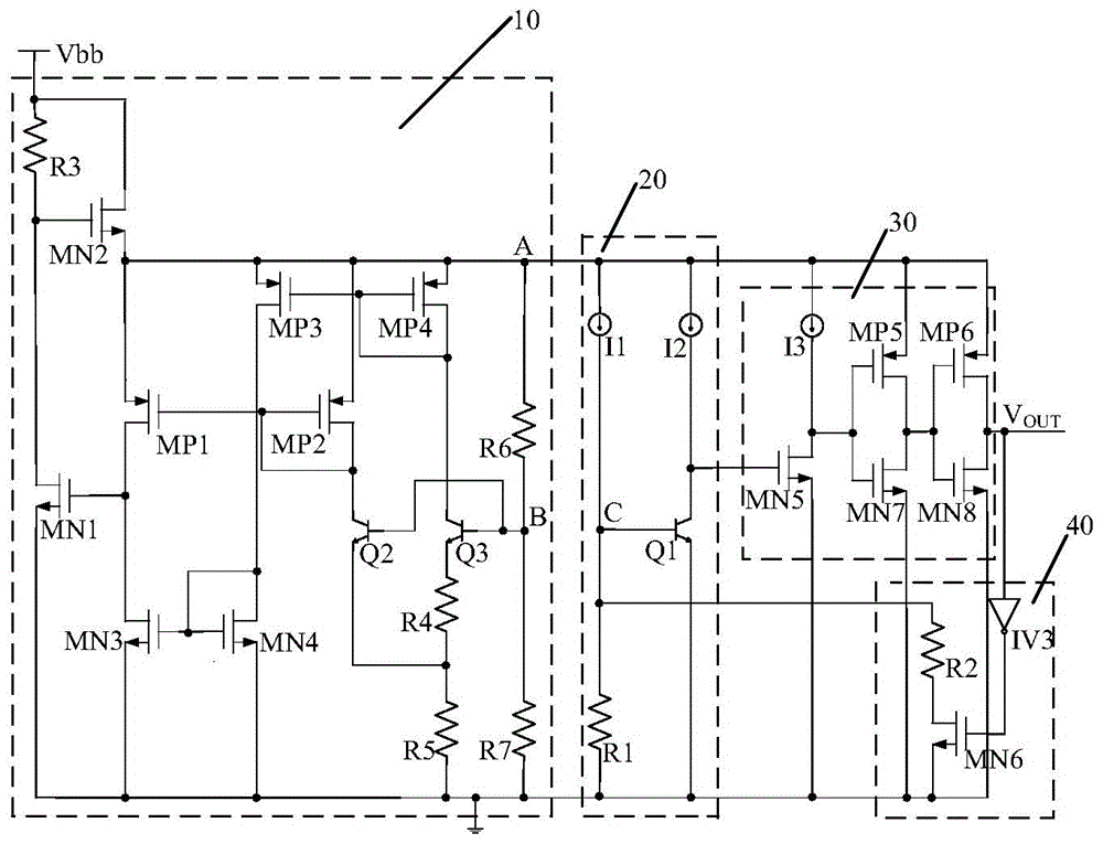
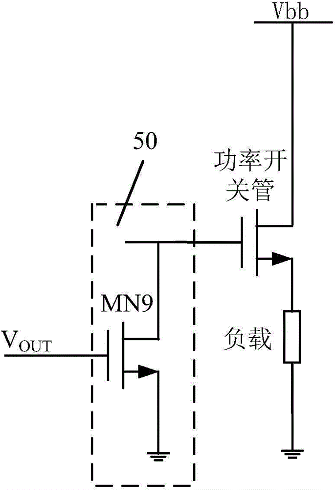
[0029] Such as figure 1 As shown, an over-temperature protection circuit for a high-side power switch includes: a reference voltage generation module 10, a temperature detection module 20, an output control and shaping module 30, a positive feedback hysteresis module 40 and a protection module 50, wherein,

[0030]The input end of the reference voltage generating module 10 is connected to the power supply voltage, and generates a stab...


PUM


Abstract

The invention discloses an over-temperature protection circuit used for a high-side power switch. The over-temperature protection circuit concretely comprises a reference voltage generation module, a temperature detection module, an output control and shaping module, a positive feedback retardation module and a protection module. The reference voltage generation module generates a stable voltage independent of a temperature and a power supply voltage. The temperature detection module converts a temperature signal into a voltage signal. The output control and shaping module outputs an over-temperature control signal according to change of the detection signal. The positive feedback retardation module adjusts a temperature detection signal according to the over-temperature control signal and achieves temperature retardation. The over-temperature protection circuit can be used for a power integrated circuit of a high-side power switch or the like, and a thermal turn-off threshold point cannot change along with power supply change. In addition, the over-temperature protection circuit can be well compatible with different power switch circuits inputting control levels and is suitable for high-side power switch circuits inputting control levels with various amplitudes.

Description

technical field [0001] The invention relates to an over-temperature protection circuit suitable for high-side power switches, which is suitable for the field of power integrated circuits. Background technique [0002] The high-side power switch circuit is a hybrid integrated circuit that integrates power devices, gate drive circuits and protection circuits. It is widely used in various fields. Temperature will cause thermal breakdown of the power switch tube, resulting in permanent damage to the power device. Therefore, the chip generally integrates an over-temperature protection circuit near the power tube to realize real-time monitoring of the chip temperature. When the temperature exceeds the threshold value, the power The switch tube is turned off. [0003] The traditional over-temperature protection circuit utilizes the PTAT current and the temperature-sensitive characteristics of the PN junction of the longitudinal PNP. Since the forward voltage drop of the PN junctio...

Claims


Application Information

Patent Timeline
IPC IPC(8): H02H5/04
Inventor 乔明陈钢李阳李妍月张晓菲张波
Owner UNIV OF ELECTRONICS SCI & TECH OF CHINA
Learn More