Wheel-driven fertilizer distributor

A wheel-driven fertilizer spreader technology, which is applied to fertilizer spreaders with centrifugal wheels, fertilization devices, fertilizer distributors, etc., can solve the problems of fuel consumption, high maintenance costs, and difficulty in controlling the movement of fertilizer spreaders alone, and achieve improved Ease of use effect

Inactive Publication Date: 2015-10-07
金完守
View PDF9 Cites 4 Cited by
  • Summary
  • Abstract
  • Description
  • Claims
  • Application Information

AI Technical Summary

Problems solved by technology

[0004] However, the existing fertilizer spreader, the stand-alone fertilizer spreader has the problems of high price, fuel consumption during operation, and high maintenance cost due to its independent engine.
[0005] The transfer type fertilizer spreader has a technical problem that it is difficult to control the operation of the fertilizer spreader independently because it receives the rotational force from the connected tractor and operates
[0006] In particular, the existing fertilizer spreader can only simply control the rotation of the spreading plate, so there is a problem that the operation of the shutter installed in the hopper or the conveyor cannot be individually controlled according to the needs of the worker.

Method used


Image

  • Wheel-driven fertilizer distributor
  • Wheel-driven fertilizer distributor
  • Wheel-driven fertilizer distributor

Examples


Embodiment Construction

[0034] Hereinafter, the present invention will be described in detail with reference to the drawings.

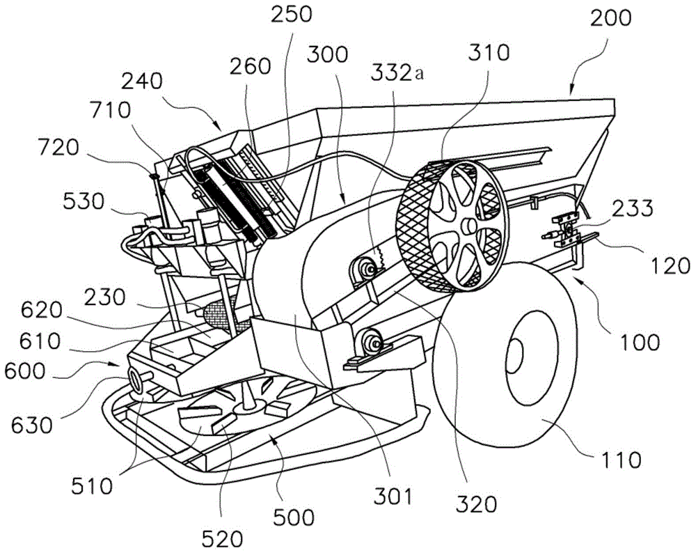
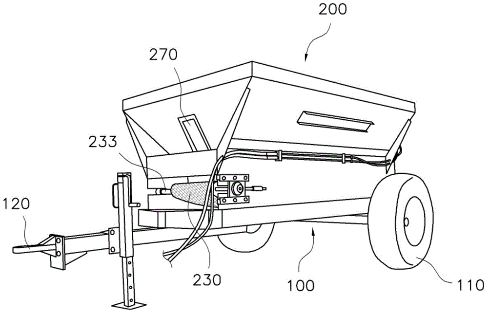
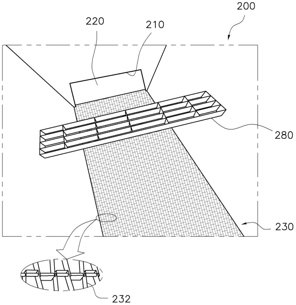
[0035] figure 1 It is a rear perspective view of the wheel-driven fertilizer spreader of the present invention, figure 2 is a front perspective view of the wheel-driven fertilizer spreader of the present invention, image 3 It is a schematic diagram showing the inside of the hopper in the wheel drive type fertilizer spreader of the present invention.

[0036] Figure 4 is a top view of the wheel-driven fertilizer spreader of the present invention, Figure 5 It is a schematic diagram of the operation of the main part of the wheel-driven fertilizer spreader of the present invention, (a) is a state diagram in which the transmission wheel is in contact with the wheel, and (b) is a state diagram in which the transmission wheel is separated from the wheel.

[0037] Figure 6 is true Figure 4 A magnified view of part A of the Figure 7 It is a schematic diagram which shows...


PUM


Abstract

The present invention relates to a wheel-driven fertilizer distributor capable of distributing a fertilizer such as compost or the like in a much easier and convenient way by controlling rotatory power transferred from a wheel to a mesh chain conveyor under hydraulic control of a tractor and by adding various functions. To this end, the present invention provides a wheel-driven fertilizer distributor capable of intermittently operating a mesh chain conveyor, a shutter, and a distributing plate of the distributor under hydraulic control of a tractor by comprising: a body frame provided with a wheel and a connection device, and moving by receiving traction from a tractor; a hopper provided on the upper part of the body frame so as to load a fertilizer, having a discharge port and a shutter on one side of the lower part thereof, and having, on the bottom surface thereof, a mesh chain conveyor for transferring the loaded fertilizer to the discharge port; a power transmission device which is provided with an electric wheel rotatably supported on the body frame, and which drives the mesh chain conveyor by transferring rotatory power received from the electric wheel that selectively comes in contact with the wheel to the mesh chain conveyor; a control device which has an elastic body and a hydraulic cylinder between the body frame and the power transmission device, and which controls the transmission of the rotatory power from the wheel to the electric wheel under the control of oil pressure supplied from the tractor; and a distributing plate which is positioned on the lower side of the discharge port of the hopper, and which distributes the fertilizer according to rotation.

Description

technical field [0001] The present invention relates to a wheel-driven fertilizer spreader, in particular to a wheel-driven fertilizer spreader. The fertilizer spreader is a fertilizer spreader that is driven by a tractor, and is transmitted from the wheels to the hopper by controlling the hydraulic control. The rotating force of the unique mesh chain conveyor and the gate of the hopper are operated at the same time, so that it is easier and more convenient to spread fertilizer. Background technique [0002] In general, a fertilizer spreader is a machine that evenly spreads various fertilizers such as compost on a rice field, and is usually used by connecting to the rear of a tractor. [0003] The fertilizer spreader needs to use a driving source to evenly spread the fertilizer loaded in the hopper. According to the driving source, it can be divided into: independent type fertilizer spreader, which drives a separate engine installed on the fertilizer spreader, and spreads f...

Claims


Application Information

Patent Timeline
IPC IPC(8): A01C15/06A01C19/00A01C15/00
CPCA01C19/00A01C15/122A01C15/124A01C17/001A01C15/00A01C15/06
Inventor 金完守
Owner 金完守
Why Eureka
Try Eureka