
Multi-functional hand warmer

A hand warmer, multi-functional technology, applied in the field of multi-functional hand warmers and hand warmers

Inactive Publication Date: 2015-10-14
周建峰
View PDF1 Cites 1 Cited by
  • Summary
  • Abstract
  • Description
  • Claims
  • Application Information

AI Technical Summary

Problems solved by technology

[0003] In order to overcome the limitation of the normal activities of the existing hand warmers when the hands are warmed and to avoid the problem of idle hand warmers, the invention discloses a multifunctional hand warmer

Method used


Image

  • Multi-functional hand warmer
  • Multi-functional hand warmer
  • Multi-functional hand warmer

Examples


Embodiment 1

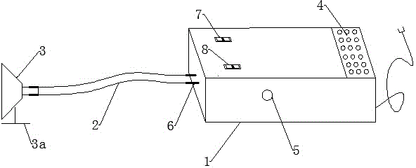
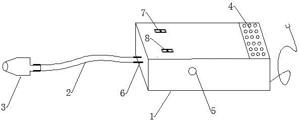
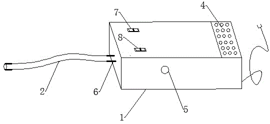
[0023] A multi-functional hand warmer comprises a heater 1, a heater delivery pipe 2, and a nozzle 3. The heater 1 is mainly composed of a bellows 9, a fan 13, a heating wire 14 and a storage box 15. The bellows 9 is composed of three parts: an air inlet section 10, a cooling and heating section 11, and an air outlet section 12. The fan 13 is located in the air inlet section 10 , the heating wire 14 is arranged in the heating and cooling section 11, and the heating and cooling section 11 is arranged in the middle of the air inlet section 10 and the air outlet section 12, and a push-pull rod 5 is connected on the side of the heating and cooling section 11, and the push-pull rod 5 can drive the heating and cooling section 11 to translate left and right . The heating and cooling section 11 is composed of two conjoined cylinders. The cylinder with heating wire inside is the hot air cylinder 11a, and the other cylinder without heating wire is the air cooler 11b. The two cylinders a...

Embodiment 2

[0030]A multi-functional hand warmer comprises a heater 1, a heater delivery pipe 2, and a nozzle 3. The heater 1 is mainly composed of a bellows 9, a fan 13, a heating wire 14 and a storage box 15. The bellows 9 is composed of three parts: an air inlet section 10, a cooling and heating section 11, and an air outlet section 12. The fan 13 is located in the air inlet section 10 , the heating wire 14 is arranged in the heating and cooling section 11, and the heating and cooling section 11 is arranged in the middle of the air inlet section 10 and the air outlet section 12, and a push-pull rod 5 is connected on the side of the heating and cooling section 11, and the push-pull rod 5 can drive the heating and cooling section 11 to translate left and right . The heating and cooling section 11 is composed of two conjoined cylinders. The cylinder with heating wire inside is the hot air cylinder 11a, and the other cylinder without heating wire is the air cooler 11b. The two cylinders ar...


PUM


Abstract

The invention relates to a small household electric appliance, more particularly to, a hand warmer. The multi-functional hand warmer comprises a heater, a heat conveying pipe, and a nozzle. The heat conveying pipe is flexibly connected to the heater. The nozzle is flexibly connected to the other end of the heat conveying pipe. The heater mainly comprises a blower, an electric heating fuse, a fan and a storing cabinet. The blower comprises three sections: a wind entering section, a cold and heating section and a wind exiting section. The cold and heating section is arranged between the wind entering section and the wind exiting section. The cold and heating section comprises two integrated cylinders with one for heated air and the other for cold air. The side face of the cold and heating section is connected with a push-and-pull rod which allows the cold and heating section to move horizontally from left to the right to make the cylinder for heated air and the cylinder for cold air work in alternation. The advantages of the invention lie in that while keeping the hands of a user warm, it does not influence the movement of the hands so that the user could work and study normally. The warmer can be used in all year round to warm hands, to blow hair, to provide coolness and to humidify. These functions make it usable even after winters. It is also energy saving, radiation free, and convenient to provide warmth.

Description

technical field [0001] The invention relates to a multifunctional hand warmer, which belongs to the field of small household appliances, in particular to a hand warmer. Background technique [0002] In the cold season, the hands and feet are often the coldest parts of our body, especially the hands. When the hands are exposed to the outside, the hands are often cold, which makes people uncomfortable and affects work. At present, there are many related electric appliances for warming hands on the market. There are two main types, one is hot water bottle, and the other is electric heating baking. The radiation is large, the power consumption is large, and the clothes are damaged. In addition, there is also an invention called "hand and foot dual-purpose heater (201320000089.2)" in the prior art, which adopts the heating method of heating, passing the heating air into a container, and then extending the hand into the container for heating. Although the invention is more comfo...

Claims


Application Information

Patent Timeline
Patent Type & Authority Applications(China)
IPC IPC(8): A61F7/08
Inventor 周建峰
Owner 周建峰
Learn More