Integrated working machine for non-excavation pipeline

A technology of non-excavation and operating machines, applied in the direction of special pipes, pipe components, mechanical equipment, etc., can solve problems such as difficult to ensure work quality, high use cost, high labor intensity, etc., to reduce pipeline operating costs and high work efficiency , The effect of low construction cost

Active Publication Date: 2011-09-28
高为人
View PDF5 Cites 14 Cited by
  • Summary
  • Abstract
  • Description
  • Claims
  • Application Information

AI Technical Summary

Problems solved by technology

[0002] At present, there is no trenchless comprehensive pipeline operation machine similar to it in pipeline engineering machinery at home and abroad. In the operation of pipeline dredging, traditional dredging techniques are basically used-pipe plugs (commonly known as buckets), pipeline brushes and pipelines. Noose, etc., or high-pressure water path technology, these traditional dredging and cleaning technologies are not only labor-intensive, but also difficult to guarantee the quality of work, especially for tree root intrusion, hard nodules, hard deposits, hard The treatment of blockage and long-distance pipeline silting is almost powerless; high-pressure water path, expensive equipment, high cost of use, and the same can not solve the root intrusion in the pipeline, hard nodules, hard silt, hard blockage and long-term The problem of distance pipeline silting is not easy to solve in developed countries; my country is still in its infancy in terms of pipeline trenchless maintenance and overhaul technology, and there is no relatively mature construction technology and construction machinery. The non-excavation cleaning, inspection, maintenance and overhaul of old pipelines need to be solved urgently, and new and effective technologies and equipment are urgently needed in order to carry out the work better

Method used


Image

  • Integrated working machine for non-excavation pipeline
  • Integrated working machine for non-excavation pipeline
  • Integrated working machine for non-excavation pipeline

Examples


Embodiment 1

[0039] Removal of hard scale in the pipe

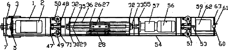
[0040] see figure 1 , figure 2 , Figure 5 , Figure 7 , Figure 8 , Figure 10 In the present invention, six mechanical units including a hard working head, a supporting machine, a pipe wall tensioning machine, a supporting machine, a screw propulsion machine, and a control box are sequentially plugged together and locked by screws to form a comprehensive non-excavation pipeline operation. machine;

[0041]The hard working head includes: the first body 1, the first motor 2 is arranged in the first body 1, the shaft of the first motor 2 passes through the front baffle 3, the sealing ring 4 is connected with the main shaft 5, and the compression nut 8 connects the elastic grinding head 6. The circular grinding head 7 is fixedly installed on the main shaft, and the first motor 2 is connected with the electric control assembly box 62;

[0042] The pipe wall tension machine includes: the second body 25, tensioner 26, fuel injectio...

Embodiment 2

[0048] Removal of soft deposits in the pipe

[0049] See image 3 , only need to replace the hard working head with the soft working head, the soft working head includes: the sixth body 9, the third motor 10, the front baffle 11, the main shaft 12, the sealing ring 13, the pipe wall brush 14, the cutting blow Head 15, compression nut 16; the body 9 is provided with a third motor 10, the motor 10 is connected to the main shaft 12 through the front baffle 11, the sealing ring 13, and the electric control assembly box 62 in the control box through the power cable The power cord is connected, and the compression nut 16 fixes the cutting head 15 and the pipe wall brush 14 on the main shaft 12.

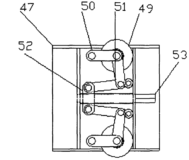
[0050] In the present invention, when it is necessary to remove sand, gravel and soil soft deposits in the pipe, the non-excavation pipeline comprehensive operation machine is placed in the pipe to be pigged, and the transmission screw 53 of the two support machines is adjusted so that eac...

Embodiment 3

[0052] In-pipe partial maintenance work

[0053] See Figure 4 In the present invention, when local overhaul operations in the pipe or treatment of residual roots in the pipe wall are required, the hard working head of the non-excavation pipeline comprehensive operation machine is replaced by a rotating fixture working head, and the rotating fixture working head includes a seventh body 17 , the fourth motor 18, the biaxial reducer 19, the front baffle 20, the seal ring 22, the rotary fixture 23, the fixture rotating motor 24; the fourth motor 18 is provided in the seventh body 17, the biaxial reducer 19, Front baffle 20, front baffle 20 inboards are equipped with biaxial reducer 19, and front baffle 20 outsides are equipped with jig rotating motor 24, and jig rotating motor 24 and the 4th motor 18 pass power cable and electric motor in the control box. The power line of control assembly box 62 is connected, the output shaft 21 of biaxial reducer 19 passes front baffle plate 2...


PUM


Abstract

The invention relates to an integrated working machine for a non-excavation pipeline, belonging to the field of engineering machinery. A rigid working head, a supporting machine, a pipe wall tensioning machine, a spiral pusher, a supporting machine and a control box are spliced to form the integrated working machine for the non-excavation pipeline. The working machine provided by the invention isspecial machinery specially used in cleaning silt, cleaning and checking the dragging and pushing operation in a pipe for a pipeline at the state of non-excavation, and can maintain the partial defects of the inner part of the pipe. The working machine has the advantages of small flooring area, low noise, rapid speed, high concealment, good enginnering safety and civilized construction, does not damage to the ground environment, does not influence traffic, the normal life and working order for people, is environmentally-friendly construction machinery, and is good helper for management pesonnel and maintaining personnel for city management; and the machine has the advantages of working efficiency, low construction cost, energy conservation, time and labor conservation, and high automoticity and is simple in operation, is convenient to maintain the pipeline, the service life of a pipe body is prolonged, the operation cost of the pipeline is reduced, and the econimoc benefit is improved.

Description

technical field [0001] The invention relates to a non-excavation pipeline comprehensive operation machine, which belongs to the field of engineering machinery. Background technique [0002] At present, there is no trenchless comprehensive pipeline operation machine similar to it in pipeline engineering machinery at home and abroad. In the operation of pipeline dredging, traditional dredging techniques are basically used-pipe plugs (commonly known as buckets), pipeline brushes and pipelines. Noose, etc., or high-pressure water path technology, these traditional dredging and cleaning technologies are not only labor-intensive, but also difficult to guarantee the quality of work, especially for tree root intrusion, hard nodules, hard deposits, hard The treatment of blockage and long-distance pipeline silting is almost powerless; high-pressure water path, expensive equipment, high cost of use, and the same can not solve the root intrusion in the pipeline, hard nodules, hard silt, h...

Claims


Application Information

Patent Timeline
Patent Type & Authority Applications(China)
IPC IPC(8): F16L55/32F16L101/12F16L101/16F16L101/30
Inventor 高为人
Owner 高为人
Why Eureka
Try Eureka