
Hydrostatic Traction Drive In Closed Hydraulic Circuit And Method For Controlling The Hydrostatic Traction Drive

A drive, hydrostatic technology, used in transmission control, hydrostatic brakes, brakes, etc., to solve problems such as drive overload

Active Publication Date: 2015-10-14
ROBERT BOSCH GMBH
View PDF8 Cites 4 Cited by
  • Summary
  • Abstract
  • Description
  • Claims
  • Application Information

AI Technical Summary

Problems solved by technology

[0007] The downside is that this is now a source of error according to the operator / driver and does not rule out human error
As a result, the mentioned overloading of the drive or accidents due to too late or too little deceleration can occur

Method used


Image

  • Hydrostatic Traction Drive In Closed Hydraulic Circuit And Method For Controlling The Hydrostatic Traction Drive
  • Hydrostatic Traction Drive In Closed Hydraulic Circuit And Method For Controlling The Hydrostatic Traction Drive
  • Hydrostatic Traction Drive In Closed Hydraulic Circuit And Method For Controlling The Hydrostatic Traction Drive

Examples


Embodiment Construction

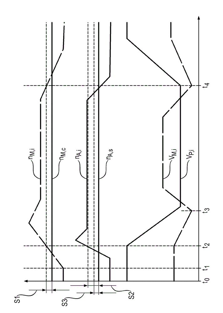
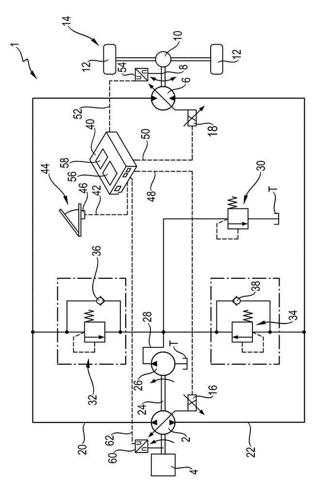
[0066] according to figure 1 , the hydrostatic traction drive 1 has a first hydrostatic hydraulic machine 2 , which operates as a hydraulic pump in a first line and is driven by a drive 4 designed as a diesel engine. Furthermore, the hydrostatic traction drive 1 has a second hydrostatic hydraulic machine 6 , which is coupled via a drive shaft 8 to a shaft 14 with two wheels 12 and acts as a hydraulic motor in the first line. run. Both hydraulic machines 2 , 6 can be adjusted with respect to their displacement volume via adjustment units 16 , 18 respectively. The first hydraulic machine 2 is fluidically connected to the second hydraulic machine 6 in a closed hydraulic circuit via a first branch line 20 , which is considered to be the preceding line on the other hand, and via a second branch line through which the pressure medium passes. The preceding line flows from the hydraulic machine 2 to the hydraulic machine 6 , said second branch being, on the other hand, a second bran...


PUM


Abstract

A hydrostatic traction drive in a closed hydraulic circuit includes two hydraulic machines in the closed hydraulic circuit and a control unit configured to control a braking torque of the traction drive. A method for controlling the hydrostatic traction drive includes controlling the braking torque for the hydrostatic traction drive.

Description

technical field [0001] The invention relates to a hydrostatic traction drive in a closed hydraulic circuit according to the preamble of claim 1 and a method for controlling the hydrostatic traction drive according to claim 10 . Background technique [0002] A hydrostatic traction drive of the type described has a hydraulic pump and a hydraulic motor, which are connected to one another in a closed hydraulic circuit via two hydrostatic working lines. The hydraulic pump can be coupled to a drive, for example a diesel engine, and the hydraulic motor can be coupled, for example, to at least one wheel to be driven or at least one shaft to be driven. [0003] There are different methods of using the closed circuit of the traction drive not only for driving but also for hydraulic braking. Especially in slow-moving vehicles, it is known that the hydraulic pump is supported on the drive during overrun mode, so that the braking effect of the drive is thus utilized. However, the maxi...

Claims


Application Information

Patent Timeline
Patent Type & Authority Applications(China)
IPC IPC(8): F16H61/40F16H61/4157
CPCB60W10/196B60T1/08B60T8/17616F16H61/40F16H61/4157B60T10/04B60T13/585F16H61/42
Inventor M.贝姆
Owner ROBERT BOSCH GMBH
Learn More