Adjustable glue pouring control mechanism

A control mechanism and glue filling technology, which is applied to the surface coating liquid device, coating, etc., can solve the problem of inability to realize the miniaturization of the glue filling control mechanism, poor glue filling control accuracy, and unadjustable glue filling speed, etc. problem, to achieve the effect of reducing volume and weight, adjustable deglue speed, and light weight

Inactive Publication Date: 2017-11-24
G & A TECH
View PDF7 Cites 0 Cited by
  • Summary
  • Abstract
  • Description
  • Claims
  • Application Information

AI Technical Summary

Problems solved by technology

[0005] The existing glue filling control mechanism has problems such as poor glue filling control accuracy, unadjustable glue filling speed, and the inability to realize the miniaturization of the glue filling control mechanism.

Method used


Image

  • Adjustable glue pouring control mechanism
  • Adjustable glue pouring control mechanism
  • Adjustable glue pouring control mechanism

Examples


Embodiment Construction

[0028] The technical solutions of the present invention will be further described below in conjunction with the embodiments shown in the accompanying drawings.

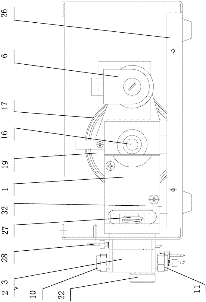
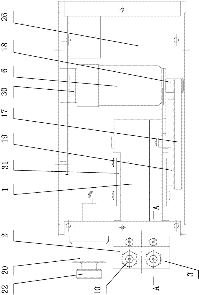
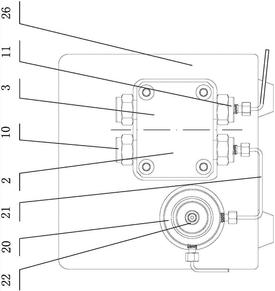
[0029] The adjustable glue filling control mechanism of the present invention, its technical scheme includes the pump body 1 installed in the pump box 26, the front end of the pump body 1 is equipped with a pump head, and the pump box 26 at the rear end of the pump body 1 is installed with an encoder 30 DC servo motor 6, the DC servo motor 6 drives the pump head on the pump body 1 to work through the synchronous pulley transmission mechanism, the pump head adopts a double-plunger parallel reciprocating pump head structure, and the pump box 26 A baffle plate 31 is provided to limit the left and right sides of the pump body 1, and the bottom of the cabinet 26 is provided with a shock absorber 32 placed below the pump body 1, such as figure 1 , figure 2 , image 3 shown.

[0030] The pump heads are the first and seco...


PUM


Abstract

Disclosed is an adjustable glue pouring control mechanism. Pump heads include a first pump head unit and a second pump head unit, and the first pump head unit and the second pump head unit are installed at the front end of a pump body in a left-and-right abreast mode. A first glue control mechanism and a second glue control mechanism are arranged in the pump body in the mode of corresponding to the first pump head unit and the second pump head unit. Each pump head unit comprises a front pump head and a rear pump head. A pump head core in the middle, an upper valve base and a lower valve base are arranged in each front pump head. A solution storage cavity is formed in each pump head core. Feeding inlets and discharging outlets of the upper valve bases and the lower valve bases are communicated with the solution storage cavities through check valves. A plunger which conducts backward return through a compression spring is arranged in each rear pump head. A piston rod at the front end of each plunger is arranged in the corresponding front pump head through a piston cavity, wherein each piston cavity is communicated between the corresponding front pump head and the corresponding rear pump head. The solution storage cavities are communicated with the piston cavities in the front pump heads, and the solution storage cavities located between the left pump head cores and the right pump head cores are communicated. The first glue control mechanism comprises a first cam and a second cam. The second glue control mechanism comprises a first cam and a second cam. The first cams and the second cams control the first glue control mechanism and the second glue control mechanism to conduct continuous glue absorption and discharge. By the adoption of the adjustable glue pouring control mechanism, the glue pouring flow is continuous and controllable, and the glue pouring speed is adjustable according to the different glue solution viscosity.

Description

technical field [0001] The invention relates to parts of a glue filling machine, in particular to an adjustable glue filling control mechanism. Background technique [0002] The glue pouring machine is also called a glue spreader, or a glue dispenser, or a glue machine, or a glue dispensing machine, etc. It is specially used to control the flow or volume of the quantitatively coated liquid glue, and apply the liquid glue to the product drop by drop or quantitatively. The automatic machine on the surface or inside the product can realize the automatic operation of multi-path glue filling and dispensing. It is widely used in internal glue filling and external packaging and fixed installation of electronic products, especially for internal glue filling or dispensing of electronic components such as electromechanical control components. Due to the small size of electronic components such as electromechanical control components, it is difficult to There are precise requirements ...

Claims


Application Information

Patent Timeline
Patent Type & Authority Applications(China)
IPC IPC(8): B05C11/10
CPCB05C11/1002
Inventor 于捷程贤科莫文礁
Owner G & A TECH
Why Eureka
Try Eureka