Device and method for detecting static azimuth misalignment angle of precision centrifuge

A technology of precision centrifuge and detection device, applied in the direction of angle/taper measurement, etc., can solve the difficulty in adjusting the coincidence of the center of the dimming path and the axis of the precision centrifuge spindle, the complex structure of the whole system, and easy to be subject to external interference, etc. problems, to avoid the adjustment process of the optical path, improve the detection efficiency, and improve the anti-interference ability.

Active Publication Date: 2017-07-28
GENERAL ENG RES INST CHINA ACAD OF ENG PHYSICS
View PDF6 Cites 0 Cited by
  • Summary
  • Abstract
  • Description
  • Claims
  • Application Information

AI Technical Summary

Problems solved by technology

Since this method needs to install two 45° reflectors on the top and outside of the precision centrifuge spindle, and the light of the dual-axis dynamic photocollimator is also transmitted through the outside, it cannot be used in many space-effective conditions and is easily affected by the outside world. interference; secondly, it is difficult to adjust the coincidence degree between the center of the optical adjustment path and the shaft center of the precision centrifuge, and the efficiency is low; moreover, the entire system required by this detection method is complex and costly

Method used


Image

  • Device and method for detecting static azimuth misalignment angle of precision centrifuge
  • Device and method for detecting static azimuth misalignment angle of precision centrifuge
  • Device and method for detecting static azimuth misalignment angle of precision centrifuge

Examples


Embodiment Construction

[0021] The present invention will be further described below in conjunction with accompanying drawing:

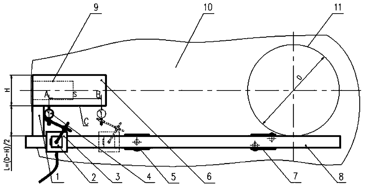
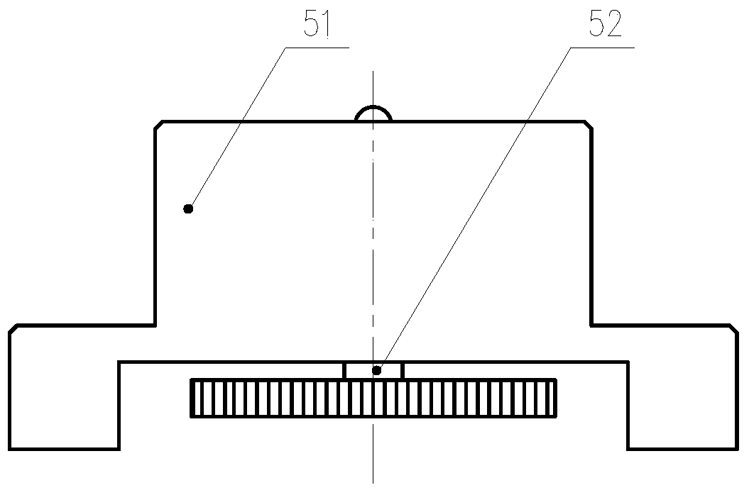
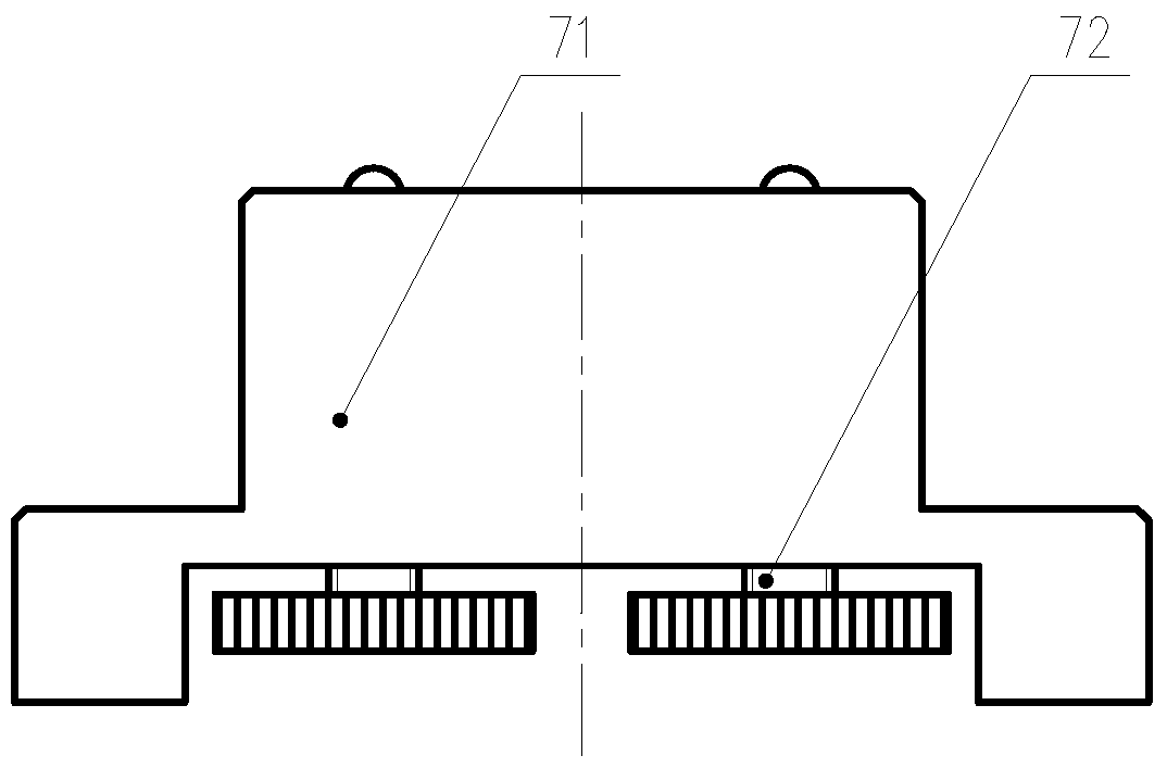
[0022] Such as figure 1 , figure 2 with image 3 As shown, the present invention includes a precision mounting base 6 for installing the test piece 9 and an air-floating square rail 8 with an air-floating sliding sleeve 3. The precision mounting base 6 is fixedly installed on the load end of the rotary arm 10 of the precision centrifuge. The floating square rail 8 is installed horizontally on the rotating arm 10, the precision mounting seat 6 is a cuboid structure, the precision mounting seat 6 is parallel to the air-floating square rail 8, and one side of the precision mounting seat 6 is used as the measuring surface C and is facing the air-floating square A gauge block 1 with a rectangular parallelepiped structure is arranged between the rail 8, the air-floating square rail 8 and the precision mount 6. The gauge block 1 is located on the end of the precision mount 6 aw...


PUM


Abstract

The invention discloses a device for detecting a static azimuth misalignment angle of a precise centrifuge and a method thereof. The device comprises the components of a precise mounting base for mounting a detected member, an air floatation square rail with an air floatation sliding sleeve, a gauge block, a magnetic meter rack and a dial gauge. One end surface of the gauge block closely abuts against the measuring surface of the precise mounting base. The air floatation square rail simultaneously abuts against the other end surface of the gauge block and the external surface of a rotary main shaft. The dial gauge is mounted on the magnetic meter rack. The magnetic meter rack is mounted on the air floatation sliding sleeve. In detection, the air floatation sliding sleeve slides from a certain point at one end of the a measuring surface of the precise mounting base to another certain point at the other end along with the magnetic meter rack and the dial gauge. The static azimuth misalignment angle of the precise centrifuge can be obtained dividing an indication difference of the dial gauge between the two position points by a distance between the two points and computing an antitangent value of an obtained value. The device and the method have advantages of settling a problem of high difficulty in detecting the static azimuth misalignment angle on condition of limited space, simplifying a system, improving an interference resistance, realizing lower cost, improving detecting efficiency and reducing detecting cost.

Description

technical field [0001] The invention relates to a static azimuth misalignment angle detection device and method for a precision centrifuge, which belongs to the technical field of inertial device testing equipment and can be applied to the inspection, verification and test of a precision centrifuge. Background technique [0002] The existing method for measuring the static azimuth misalignment angle of a precision centrifuge is to use a dual-axis dynamic photoelectric collimator method: the accelerometer is mounted on a precision mount, a 45° moving mirror is installed on the axis of the main shaft, and a mirror is placed on the top of the main shaft. Install a 45° static mirror in the space, and finally install a dual-axis dynamic photoelectric collimator in the top space of the precision centrifuge, adjust the optical path so that the center of the optical path coincides with the axis of the precision centrifuge spindle and merge on the reflective surface of the precision m...

Claims


Application Information

Patent Timeline
Patent Type & Authority Patents(China)
IPC IPC(8): G01B5/24
Inventor 张映梅黎启胜卢永刚贾晓英张瑞杰潘勤勇马庆伟刘建杰
Owner GENERAL ENG RES INST CHINA ACAD OF ENG PHYSICS
Why Eureka
Try Eureka