Single-air-outlet spin-coating development cavity

An air outlet and glue cavity technology, which is applied in the field of single air outlet and glue developing cavity to reduce the number of air outlets, improve airflow uniformity, and reduce volume.

Inactive Publication Date: 2015-10-14
SHENYANG KINGSEMI CO LTD
View PDF5 Cites 0 Cited by
  • Summary
  • Abstract
  • Description
  • Claims
  • Application Information

AI Technical Summary

Problems solved by technology

The cavity solves the problem of uniform air flow inside the developing cavity

Method used


Image

  • Single-air-outlet spin-coating development cavity
  • Single-air-outlet spin-coating development cavity
  • Single-air-outlet spin-coating development cavity

Examples


Embodiment Construction

[0026] The present invention will be described in further detail below in conjunction with the accompanying drawings.

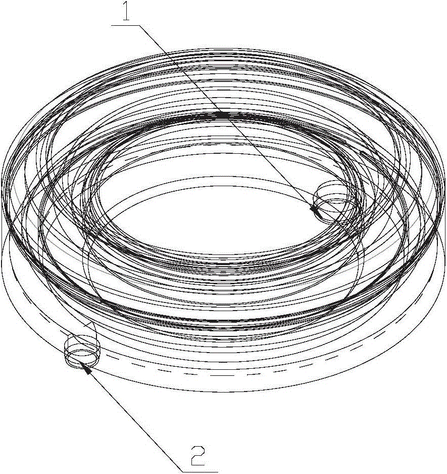
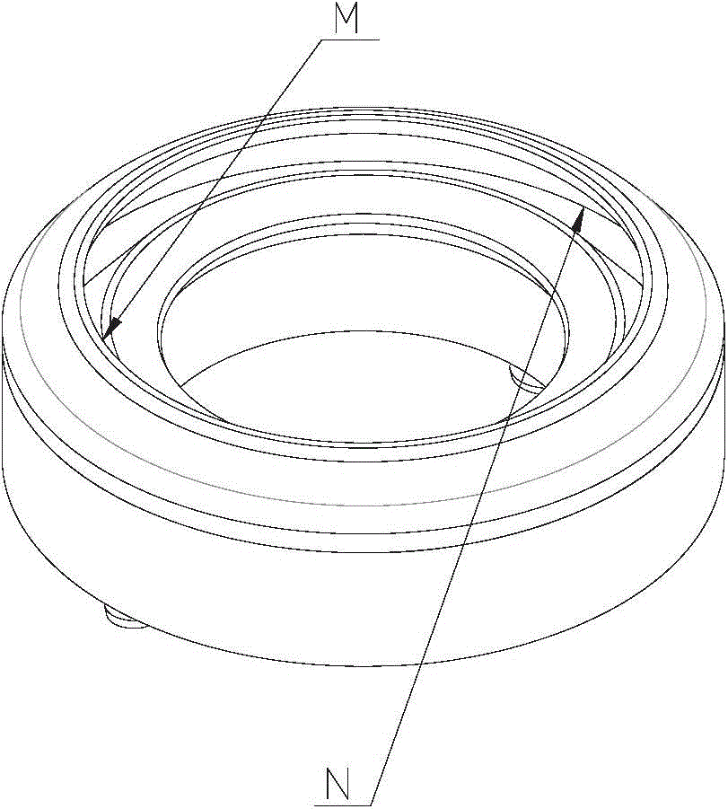
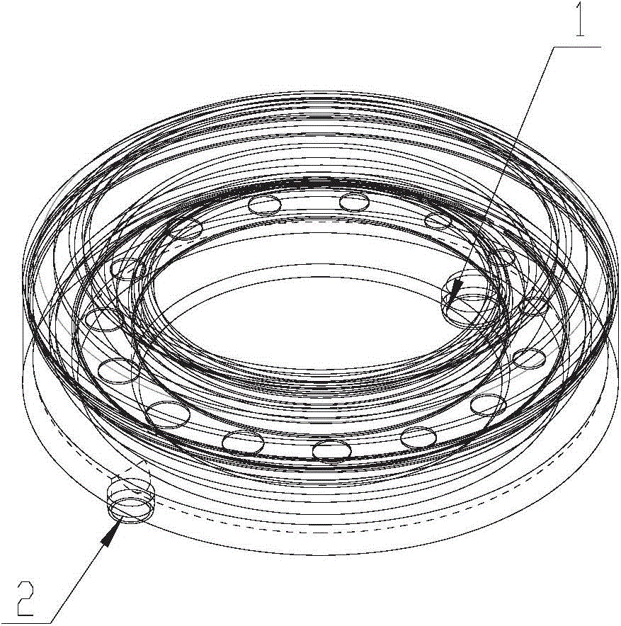
[0027] Such as Figure 3-5 As shown, the present invention includes an upper glue-distributing chamber 3, a middle glue-distributing chamber 4, a rectifying plate 5 and a lower glue-distributing chamber 6, wherein the bottom of the lower glue-distributing chamber 6 is provided with an air outlet 1, and the The top of the lower glue uniform cavity 6 is provided with an upper glue uniform cavity 3, and a middle glue uniform cavity 4 is arranged between the upper glue uniform cavity 3 and the lower glue uniform cavity 6, and the rectifying plate 5 is arranged on Between the exhaust vent 1 and the wafer.

[0028] The bottom of the lower glue uniform cavity 6 is provided with an extension inwardly, the middle glue uniform cavity 4 is arranged on the extension, and the rectifying plate 5 is installed on the extension by a positioning structure 8, And it is locate...


PUM


Abstract

The invention relates to a spin-coating development device in the field of semiconductor manufacturing, and particularly provides a single-air-outlet spin-coating development cavity, which includes an upper spin-coating cavity, a middle spin-coating cavity, a flow reshaping board and a lower spin-coating cavity. The bottom of the lower spin-coating cavity is provided with an air outlet. The upper spin-coating cavity is disposed on the top of the lower spin-coating cavity. The middle spin-coating cavity is disposed between the upper spin-coating cavity and the lower spin-coating cavity. The flow reshaping board is arranged between the air outlet and a wafer, is in an annular shape and is provided with a plurality of holes circumferentially therein. The device is reduced in the number of air outlets and is reduced in size, and is improved in uniformity of air flow neighboring the waver.

Description

technical field [0001] The invention relates to a glue leveling and developing device in the field of semiconductor manufacturing, in particular to a glue leveling and developing chamber with a single row of air outlets, which is used to optimize the airflow field characteristics in the glue leveling and developing process chamber. Background technique [0002] For photoresist coating in the field of semiconductor manufacturing, it is a very common process realization method. Its basic features are: the wafer is adsorbed on a circular chuck, and after the photoresist is sprayed on the surface of the wafer, the chuck drives the wafer Rapid rotation spreads the photoresist evenly on the wafer surface. The whole process is carried out in a process chamber, which is often called a cup in the industry, which has the functions of collecting waste liquid and exhausting air. [0003] During the cup exhaust process, the internal airflow field distribution has a great influence on th...

Claims


Application Information

Patent Timeline
Patent Type & Authority Applications(China)
IPC IPC(8): G03F7/30
Inventor 刘莹
Owner SHENYANG KINGSEMI CO LTD
Why Eureka
Try Eureka