Eureka AIR delivers breakthrough ideas for toughest innovation challenges, trusted by R&D personnel around the world.

Planetary gear bearings in planetary drives

A planetary gear and support device technology, which is applied to transmission parts, rotating bearings, engine components, etc., can solve the problems of reducing the sliding friction of the stopper, failing to meet high energy efficiency, and lubricant clogging.

Active Publication Date: 2017-09-22
SCHAEFFLER TECH AG & CO KG
View PDF3 Cites 0 Cited by
  • Summary
  • Abstract
  • Description
  • Claims
  • Application Information

AI Technical Summary

Problems solved by technology

[0004] However, a disadvantage of this type of planetary gear bearing is that, due to the use of stop discs between the planet gears and the planet carrier, high power losses are caused due to the sliding friction that occurs between the stop discs and the planet gears, therefore, The energy efficiency required in modern automatic transmissions for passenger cars cannot be met with such planetary drives
Likewise, the known measures on the stop plate for improving the lubricant flow through the radial rolling bearing have proven to be insufficient, because the recesses in the stop plate are guided through the stop plate. The lubricant flow is prevented by the side wall of the planet carrier arranged on the back side of the stop plate, and therefore an undesired lubricant blockage always occurs in the radial rolling bearing of the planet gear
Furthermore, the known planetary gear bearings have also proven to be disadvantageous with regard to the cost-intensive production and assembly of the planet gears, since in order to reduce the sliding friction with the stop plate, grinding and honing for individual surface treatment

Method used


Image

  • Planetary gear bearings in planetary drives
  • Planetary gear bearings in planetary drives
  • Planetary gear bearings in planetary drives

Examples


Embodiment Construction

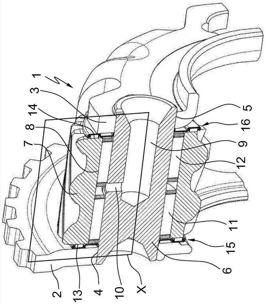
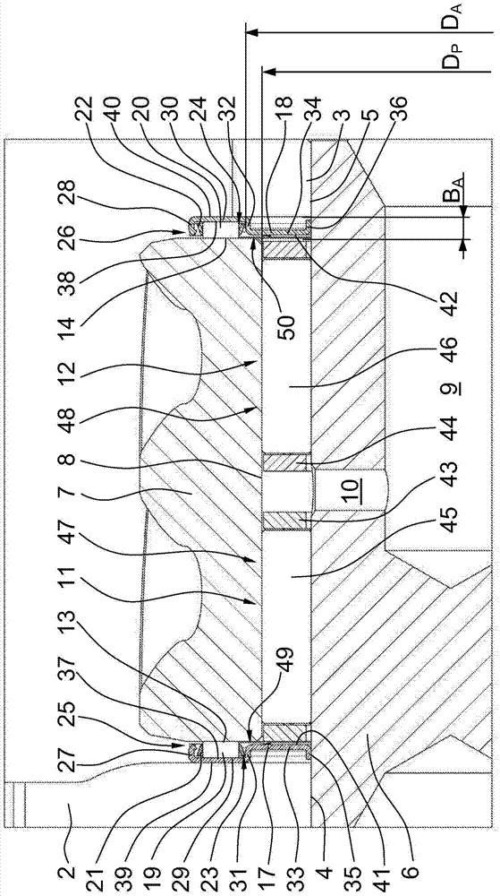
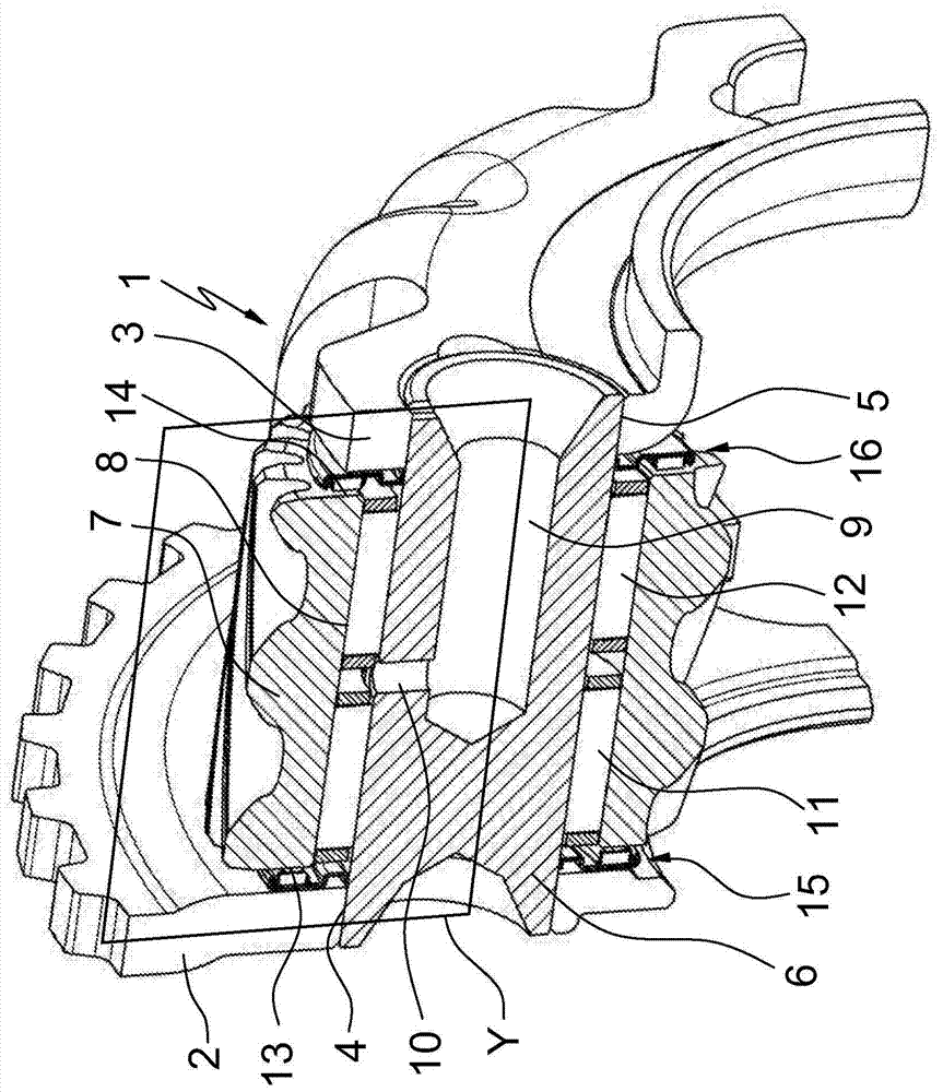
[0022] figure 1 , image 3 and Figure 5 Each clearly shows a planetary gear carrier in a planetary gear, which essentially consists of a planetary carrier 1 with two side walls 2 , 3 arranged parallel to one another, which are arranged in a plurality of The coaxially opposite axial bores 4 , 5 each receive a plurality of planet gear pins 6 . Here, a plurality of planetary gears 7 are rotatably mounted on the planetary pin 6 via radial rolling bearings 11 , 12 inserted in the central planetary bore 8 , which are mounted via shafts inside the planetary pin 6 . The radial and radial lubricant supply lines 9 , 10 are continuously lubricated. Furthermore, between the side walls 2 , 3 of the planetary carrier 1 and the axial sides 13 , 14 of the planetary gears 7 there are ring-plate-shaped stop elements 15 , 16 , which are designed as the pins of the planetary carrier 1 . The wear protection part and the wear protection part of the planet gear 7 are also designed as axial stop...


PUM


Abstract

A planet gear bearing in a planetary gearset including a planet carrier having two side walls which are arranged parallel to one another and accommodate a plurality of planet gear pins in a plurality of axial holes opposite one another on the same axis is disclosed. A plurality of planet gears are rotatably mounted on the planet gear pins by radial rolling-element bearings inserted into central planet gear holes. Stop elements are arranged between the side walls of the planet carrier and the axial sides of the planet gears and act as wear protection of the planet carrier and the planet gears, and as an axial stop for the radial rolling-element bearings of the planet gears. The stop elements are axial needle bearings, which each include an axial bent-up disc and an axial needle ring formed by a plurality of bearing needles and an axial needle cage.

Description

technical field [0001] The invention relates to a planetary gear bearing in a planetary gear according to the features formed by the preamble of claim 1 and which particularly advantageously realizes the arrangement of planetary gears in automatic transmissions for passenger cars. in the transmission mechanism. Background technique [0002] A common embodiment of automatic transmissions for passenger cars is the so-called torque converter, which differs from conventional shift transmissions and automatic shift transmissions primarily in the shifting process without interruption of tractive force. This type of automatic transmission for passenger cars has at least one hydraulic torque converter as a starting clutch and is basically assembled from a combination of a plurality of diaphragm clutches and a plurality of idler wheels and a planetary transmission. In this case, all shifting and clutching processes are carried out via multi-disk clutches, which establish a force-loc...

Claims


Application Information

Patent Timeline
Patent Type & Authority Patents(China)
IPC IPC(8): F16H57/08F16C19/30F16H57/04
CPCF16H57/082F16C19/28F16C19/30F16C19/305F16C19/381F16C33/581F16C33/588F16C33/60F16C33/6677F16C33/6685F16C2361/61F16H57/0479F16H2057/085
Inventor 沃尔夫冈·富格尔马丁·盖格纳
Owner SCHAEFFLER TECH AG & CO KG
Why Eureka
Eureka Blog
Learn More